Non-excitation switch wiring structure and transformer

An excitation switch and transformer technology, applied in the field of transformers, can solve the problems of non-conduction of tap lines, unreliable connection, large ratio error, etc., and achieve the effects of prolonging life, reliable connection and reducing ratio error.

Pending Publication Date: 2022-06-28
BAODING TIANWEI BAOBIAN ELECTRICAL
View PDF0 Cites 0 Cited by
  • Summary
  • Abstract
  • Description
  • Claims
  • Application Information

AI Technical Summary

Problems solved by technology

[0004] However, in the above structure, there will be a gap after the short-circuit copper bar and the crimping joint of the transformer branch line are connected and compressed, which is not a reliable connection. During operation, the contacts will heat up and even generate an arc. In severe cases, the branch line may not conduct current. , there is no induced voltage on the secondary side, and the transformation ratio error is large

Method used


Image

  • Non-excitation switch wiring structure and transformer
  • Non-excitation switch wiring structure and transformer
  • Non-excitation switch wiring structure and transformer

Examples


Embodiment 1

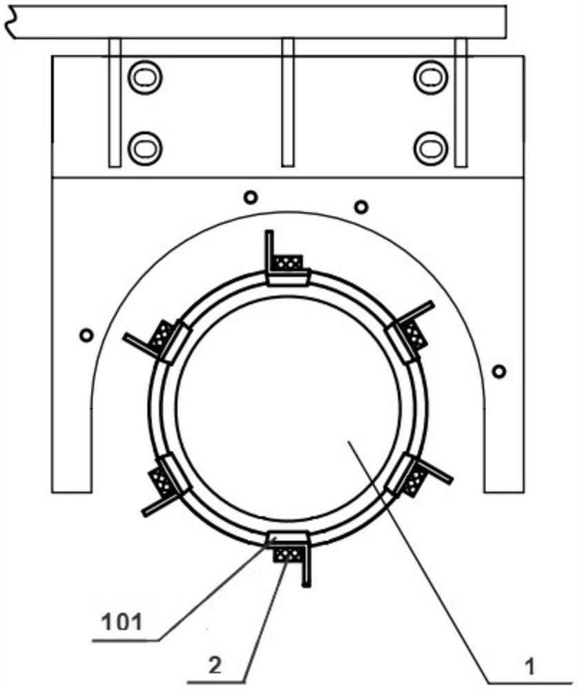
[0031] The embodiment of the present invention provides a non-excitation switch connection structure, figure 1 It is a schematic diagram of the connection structure of the non-excitation switch provided by the embodiment of the present invention. like figure 1 shown, the non-excitation switch wiring structure includes such as figure 1 The non-excited switch 1, short-circuit copper bar 2 and transition lead 3 are shown. The non-excited switch 1 includes a fixed contact 101 ; the short-circuit copper bar 2 includes a first surface and a second surface, and the first surface and the second surface are opposite surfaces. The fixed contact 101 is connected to the first surface of the shorting copper bar 2 , and the transition lead 3 is connected to the second surface of the shorting copper bar 2 .

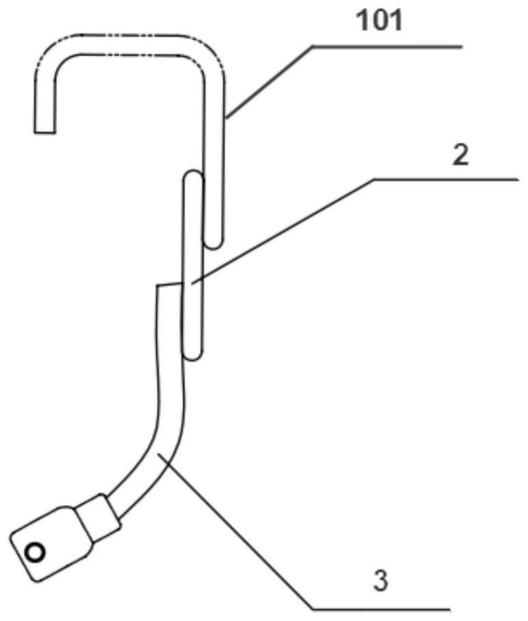
[0032] like figure 2 As shown, the fixed contact 101 is a J-shaped structure, including a long side, a short side and a curved portion, the long side is connected with the short si...

Embodiment 2

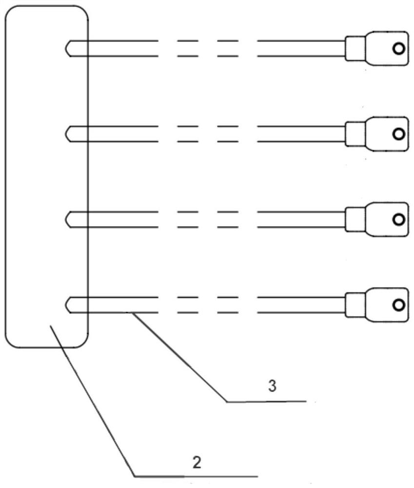
[0039] Based on the foregoing embodiments, the non-excitation switch connection structure proposed in this embodiment takes into account the requirements of the number of transformer connections and reliability, and can be better applied to transformer application scenarios. The non-excitation switch connection structure proposed in this embodiment includes a non-excitation switch 1 , a short-circuit copper bar 2 and a transition lead 3 . The non-excited switch 1 includes a fixed contact 101 ; the short-circuit copper bar 2 includes a first surface and a second surface, and the first surface and the second surface are opposite surfaces. The fixed contact 101 is connected to the first surface of the shorting copper bar 2 , and the transition lead 3 is connected to the second surface of the shorting copper bar 2 . The fixed contact 101 is a J-shaped structure, including a long side, a short side and a curved portion, the long side is connected to the short side through the curve...

Embodiment 3

[0042] Based on the foregoing embodiments, the present invention further provides a transformer, wherein the transformer includes the non-excitation switch wiring structure described in any one of the foregoing embodiments 1-2. Please note that the technical features of the above embodiments can be combined arbitrarily. In order to simplify the description, all possible combinations of the technical features in the above embodiments are not described. However, as long as there is no contradiction in the combination of these technical features , should be considered to be within the scope of this specification. The above examples only represent several embodiments of the present invention, and the descriptions thereof are specific and detailed, but should not be construed as a limitation on the scope of the invention patent. It should be pointed out that for those skilled in the art, without departing from the concept of the present invention, several modifications and improvemen...


PUM


Abstract

The invention provides a non-excitation switch wiring structure and a transformer. The non-excitation switch wiring structure comprises a non-excitation switch, a short-circuit copper bar and a transition lead, the non-excitation switch comprises a fixed contact; the short-circuit copper bar comprises a first surface and a second surface, and the first surface and the second surface are opposite surfaces; the fixed contact is connected with the first surface of the short-circuit copper bar, and the transition lead is connected with the second surface of the short-circuit copper bar. The non-excitation wire connecting structure is used for connecting a plurality of tapping leads of the transformer, so that the tapping requirement of the transformer is met; the transition lead is reliably connected with the tapping lead of the transformer, so that the probability of fixed contact heating and arc generation during operation is reduced, and the transformation ratio error is reduced; and the transition leads are connected with the tapping leads of the transformer, and the plurality of transition leads are not limited by a traction force, so that the non-excitation switch is prevented from being damaged, and the service life of the non-excitation switch is prolonged.

Description

technical field [0001] The invention relates to the technical field of transformers, in particular to a non-excitation switch connection structure and a transformer. Background technique [0002] Non-excitation switch is a type of switch, suitable for three-phase oil-immersed transformers with rated voltage of 10KV and rated current of 63A or 125A or less. Adjust the output voltage of the transformer. The temperature of the non-excited switch in the oil medium is as low as -25°C and as high as 100°C. As one of the core components of the transformer, the non-excitation switch plays the role of regulating the high-voltage side voltage and connecting the high-voltage leads in the entire transformer structure. [0003] The non-excitation switch structure comes with U, V, W three-phase static contacts, and the number of static contacts cannot meet the number of contacts required by the transformer tap lead. It is necessary to change the number of 3 contacts that come with the s...

Claims


Application Information

Patent Timeline
Patent Type & Authority Applications(China)
IPC IPC(8): H01H9/00H01H9/30H01F29/04H01F27/29
CPCH01H9/0016H01H9/30H01F29/04H01F27/29
Inventor 唐春颖李楠李晨曦杨静谢辉赵丽杰
Owner BAODING TIANWEI BAOBIAN ELECTRICAL
Why Eureka
Try Eureka