
Visual photovoltaic power generation energy consumption detection device

A detection device and photovoltaic power generation technology, applied in the direction of photovoltaic power generation, photovoltaic system monitoring, photovoltaic modules, etc., can solve the problems of internal electrical components and circuit damage, affecting the service life of the device, dust ingress, etc., to ensure life safety and property The effect of safety, reducing the risk of mishandling, and speeding up the flow

Pending Publication Date: 2022-06-28
XUZHOU COLLEGE OF INDAL TECH
View PDF0 Cites 0 Cited by
  • Summary
  • Abstract
  • Description
  • Claims
  • Application Information

AI Technical Summary

Problems solved by technology

[0003] However, the existing energy consumption detection devices for photovoltaic power generation cannot be visualized, and all data must be transmitted to the terminal to be seen, which may easily lead to misoperation due to data reception delays, and low work efficiency; poor heat dissipation performance, in the long-term detection During the process, it is easy to cause damage to the internal components of the detection device due to excessive temperature, and when the humidity in the external environment is high, it is also easy to cause damage to the internal electrical components and circuits, and during the heat dissipation process, a large amount of dust will enter, and the internal circuit Components entering the dust will seriously affect the service life of the internal circuit components and affect their use effect; at the same time, the shock absorption effect of the device is usually not obvious. When the protective device collides or moves, there will usually be a large vibration inside. In the long run, it will make the parts loose and affect the service life of the device, and it will also endanger the life safety and property safety of the staff

Method used


Image

  • Visual photovoltaic power generation energy consumption detection device
  • Visual photovoltaic power generation energy consumption detection device
  • Visual photovoltaic power generation energy consumption detection device

Examples


Embodiment Construction

[0024] In order to facilitate the understanding of the technical means, creation features, and effects achieved by the present invention, the present invention will be further described below with reference to the specific embodiments.

[0025] In the description of the present invention, it should be noted that the terms "upper", "lower", "inner", "outer", "front end", "rear end", "two ends", "one end" and "the other end" The orientation or positional relationship indicated by etc. is based on the orientation or positional relationship shown in the accompanying drawings, and is only for the convenience of describing the present invention and simplifying the description, rather than indicating or implying that the indicated device or element must have a specific orientation, with a specific orientation. The orientation configuration and operation are therefore not to be construed as limitations of the present invention. Furthermore, the terms "first" and "second" are used for ...


PUM


Abstract

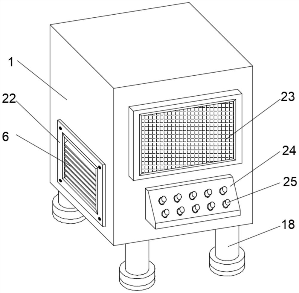
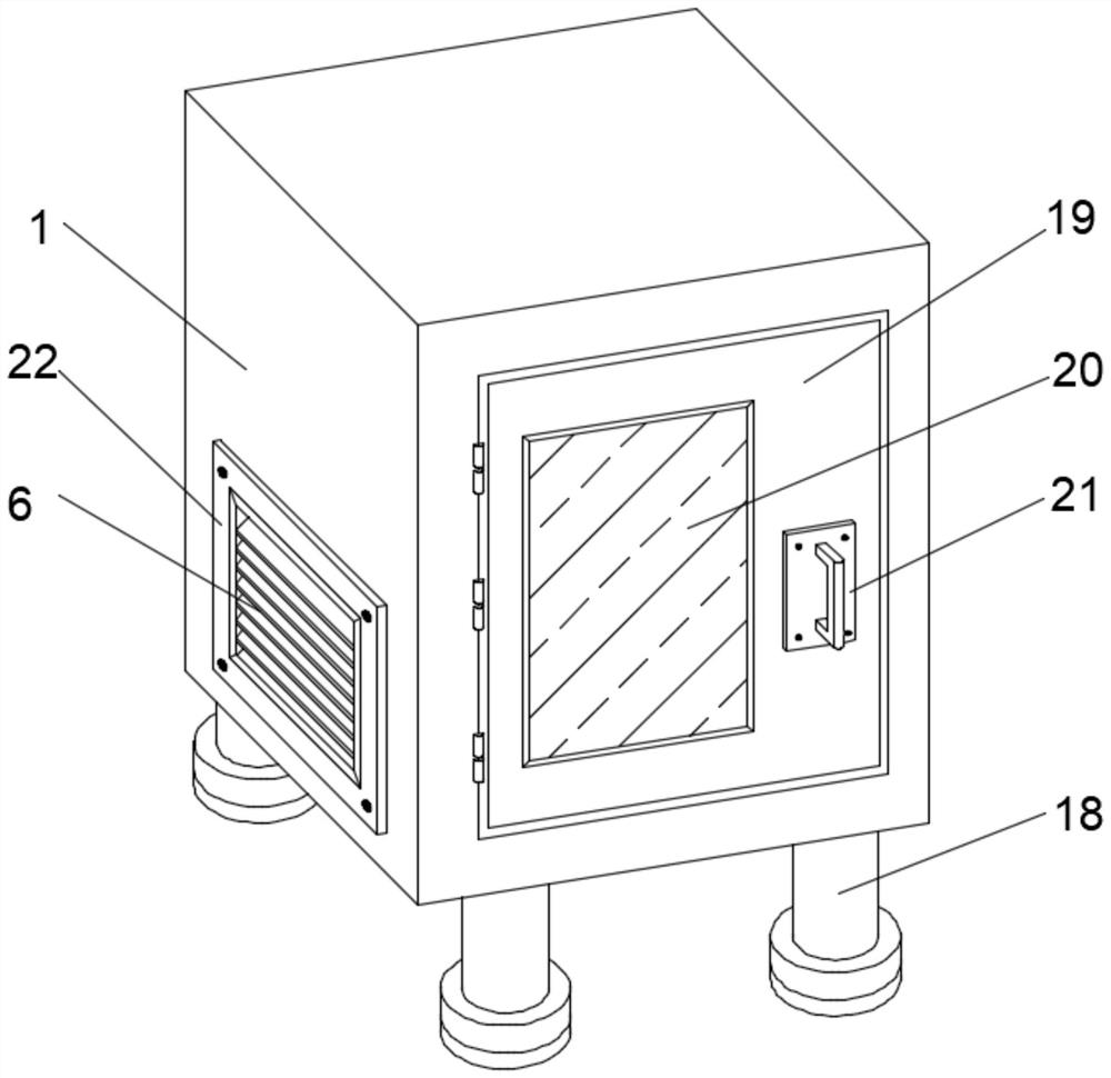
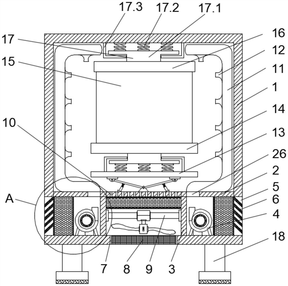
The visual photovoltaic power generation energy consumption detection device comprises a machine body, the bottom of an inner cavity of the machine body is fixedly connected with a first heat dissipation device and a second heat dissipation device, the top of a baffle is fixedly connected with a first buffer device, a bottom plate, an energy consumption detection module, a top plate and a second buffer device in sequence, and one side of the machine body is provided with a display screen, an operation module and the like. According to the energy consumption detection device for visual photovoltaic power generation, the display screen and the operation module are arranged, so that subsequent operation of workers is facilitated, and the working efficiency is improved; by arranging the heat dissipation device I and the heat dissipation device II, the working temperature in the energy consumption detection device is effectively reduced, the influence of external moisture on the use effect is reduced, and the dustproof effect is effectively improved; under the buffering effect of the first buffering device and the second buffering device, the device body is not prone to collapsing or colliding with other objects, internal parts are not prone to loosening, and therefore life safety and property safety of workers are guaranteed.

Description

technical field [0001] The invention relates to the technical field of photovoltaic power generation detection, in particular to a visual photovoltaic power generation energy consumption detection device. Background technique [0002] In recent years, photovoltaic battery packs have become more and more widely used in civil and industrial production. In order to ensure the continuous and stable operation of the system, it is necessary to research and design a high-efficiency, low-cost, accurate, convenient, fast and practical photovoltaic battery pack energy consumption detection system. The voltage of the single cell of the group is low, and it is rarely used directly in its natural form. Most of them are connected in series or in series-parallel combination. To ensure the same working characteristics of each single photovoltaic battery pack in the combination, reasonable monitoring equipment must be used to detect the charge and discharge voltage and temperature of each si...

Claims


Application Information

Patent Timeline
IPC IPC(8): H02S50/00H02S50/10H05K7/20
CPCH02S50/00H02S50/10H05K7/20136Y02E10/50
Inventor 李美凤
Owner XUZHOU COLLEGE OF INDAL TECH
Learn More