Underwater pipe laying robot and pipe laying method thereof
A robot and pipe-laying technology, which is used in underwater operation equipment, pipes/pipe joints/fittings, motor vehicles, etc.
- Summary
- Abstract
- Description
- Claims
- Application Information
AI Technical Summary
Problems solved by technology
Method used
Image
Examples
Embodiment 1
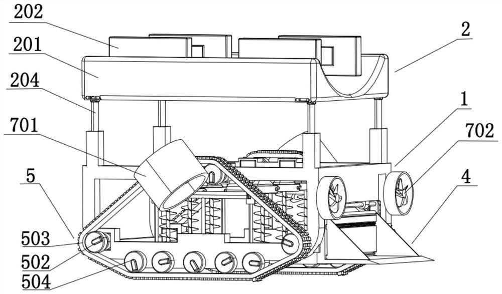
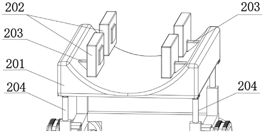
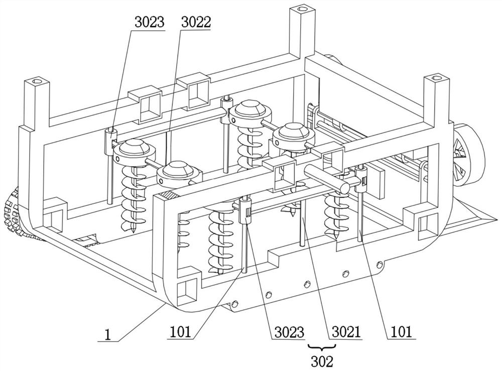
[0065] like figure 1 As shown, this embodiment discloses an underwater pipe-laying robot, including a support structure 1, a pipe-laying adsorption platform 2, a pipeline trench excavation device 3, a dust cleaning device 4, a driving device 5, a crawler adsorption device 6, and a propulsion device 7; The pipe-laying adsorption platform 2 includes a pipe-laying rack 201, several electromagnet clips 202 and a first telescopic structure. The pipe-laying rack 201 is arranged on the top of the bracket structure 1 through several first telescopic structures, and several electromagnet clips 202 pass through a plurality of first telescopic structures. The first telescopic rods 203 are arranged on both sides of the inner wall of the pipe-laying frame 201; the pipeline trench excavation device 3 is arranged at the bottom of the support structure 1, and the pipeline excavation device includes several ground drilling structures 301 and second telescopic structures 302. Several ground dril...
Embodiment 2
[0068] like Figure 1 to Figure 8 As shown, this embodiment, on the basis of Embodiment 1, discloses an underwater pipe-laying robot, including a support structure 1, a pipe-laying adsorption platform 2, a pipe trench excavation device 3, a dust cleaning device 4, a driving device 5, and a crawler belt. The adsorption device 6, the propulsion device 7; the pipe-laying adsorption platform 2 includes a pipe-laying rack 201, several electromagnet clips 202 and a first telescopic structure, and the pipe-laying rack 201 is arranged on the top of the support structure 1 through several first telescopic structures, Several electromagnet clips 202 are arranged on both sides of the inner wall of the pipe-laying frame 201 through the first telescopic rods 203; the pipeline trench excavation device 3 is arranged at the bottom of the support structure 1, and the pipeline excavation device includes several ground drilling structures 301 and a second telescopic structure 301. Structure 302,...
Embodiment 3
[0085] like Figure 10 As shown, this embodiment, on the basis of Embodiment 2, discloses a pipe laying method of an underwater pipe laying robot, comprising the following steps:
[0086] S1: The underwater pipe-laying robot is adsorbed on the mother ship through the crawler adsorption device 6, and walks on the surface of the mother ship;
[0087] S2: Disconnect the power system of the crawler adsorption device 6, and the underwater pipe-laying robot cancels the adsorption on the surface of the mother ship, so that the mother ship can drop the underwater pipe-laying robot in the ideal placement position;
[0088] S3: The propulsion device 7 operates to push the underwater pipe-laying robot to move in the water;
[0089] S4: The underwater pipe-laying robot moves to the pre-laying position on the seabed through the driving device 5;
[0090] S5: The pipeline trench excavation device 3 drives the ground drilling structure 301 to loosen soil on the seabed according to the pres...
PUM
 Abstract
Description
Claims
Application Information
 - R&D
- Intellectual Property
- Life Sciences
- Materials
- Tech Scout
- Unparalleled Data Quality
- Higher Quality Content
- 60% Fewer Hallucinations
Browse by: Latest US Patents, China's latest patents, Technical Efficacy Thesaurus, Application Domain, Technology Topic, Popular Technical Reports.
© 2025 PatSnap. All rights reserved.Legal|Privacy policy|Modern Slavery Act Transparency Statement|Sitemap|About US| Contact US: help@patsnap.com


