Sensor protection device and sensor assembling method adopting same

A protection device and sensor technology, applied in the field of sensor assembly and sensor protection device, can solve the problems of winding or breakage, inability to restore, inability to accurately measure the explosion shock wave load, etc., and achieve the effect of simple operation

Active Publication Date: 2022-07-01
BEIJING INSTITUTE OF TECHNOLOGYGY
View PDF13 Cites 0 Cited by
  • Summary
  • Abstract
  • Description
  • Claims
  • Application Information

AI Technical Summary

Problems solved by technology

However, small-scale laboratory tests and overall and local scaling tests cannot restore the real situation of the overall damage of large surface and underwater ships under the action of near-field underwater explosions, so underwater near-field explosion tests on actual ships are imperative.
[0003] However, the underwater near-field explosion test of a real ship is greatly affected by the sea conditions (such as wind and waves causing the test ship to bump up and down, and a large water flow will be formed around the test ship when driving), so that the underwater shock wave sensor used to detect the explosion shock wave It is difficult to deploy, and the sensitive components of the shock wave sensor are relatively fragile after entering the water and are easily affected by the impact of the high-speed water flow of the test ship. In addition, the transmission cable for signal connection with the data acquisition equipment is also easily impacted by the high-speed water flow and affected by the explosion shock wave If the cable is entangled or broken, the shock wave load of the underwater near-field explosion cannot be accurately measured, so a protection device for the shock wave sensor of the underwater near-field explosion is urgently needed

Method used


Image

  • Sensor protection device and sensor assembling method adopting same
  • Sensor protection device and sensor assembling method adopting same
  • Sensor protection device and sensor assembling method adopting same

Examples


specific Embodiment approach

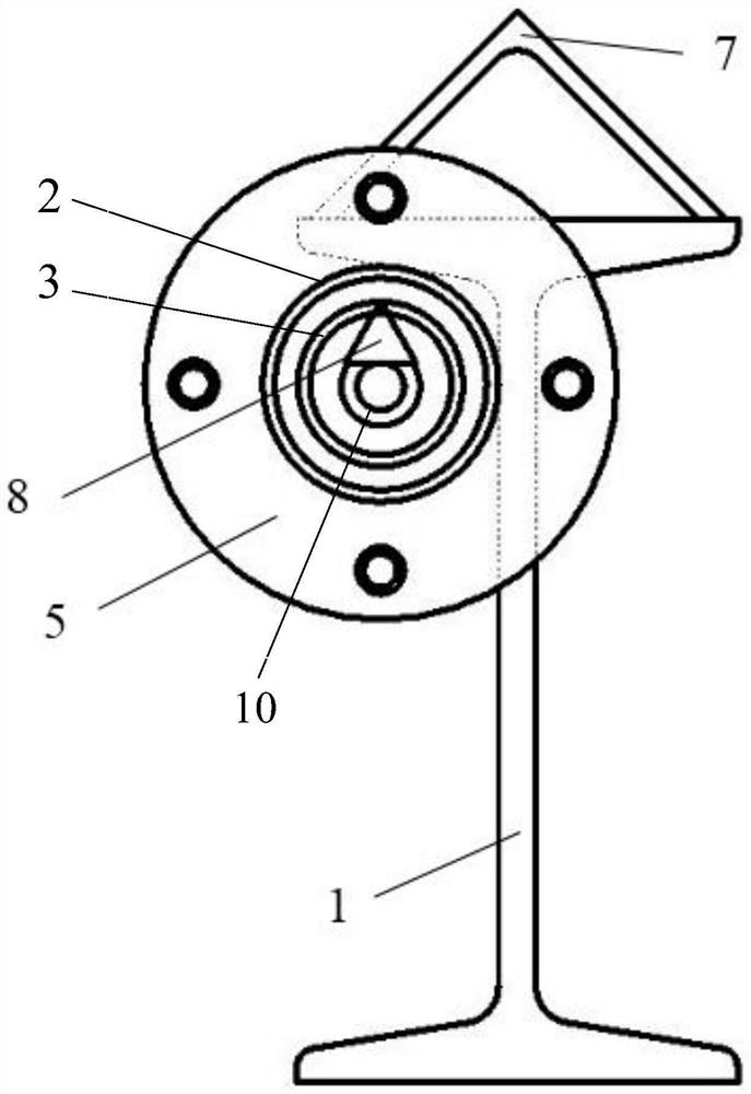
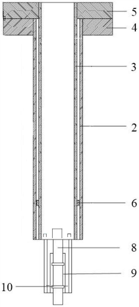
[0045] A sensor protection device such as figure 1 and figure 2As shown, the device includes: an inner pipe 3, a casing 2, an inner pipe flange 5, a casing flange 4 and a sensor fixing member. The inner pipe flange 5 is fixedly installed on one end of the inner pipe 3, the casing flange 4 is fixedly installed on one end of the casing 2, and after the inner pipe flange 5 is fixedly connected with the casing flange 4, the inner pipe 3 can pass through Set on the sleeve 2, the sensor fixing part is used to fix the sensor, one end is fixedly installed inside the end of the inner tube 3 away from the inner tube flange 5, and the other end extends out of the inner tube 3 and faces away from the inner tube 3 along the axis direction of the inner tube 3. One end of the pipe flange 5 extends; the inner pipe 3, the central through hole of the inner pipe flange 5 and the central through hole of the sleeve flange 4 are used for passing the transmission cable of the sensor.

[0046] Whe...


PUM


Abstract

The invention discloses a sensor protection device and a sensor assembling method adopting the same. The sensor protection device comprises an inner pipe, a sleeve, an inner pipe flange, a sleeve flange and a sensor fixing piece. Wherein the inner pipe flange is fixedly installed at one end of the inner pipe, the casing pipe flange is fixedly installed at one end of the casing pipe, and after the inner pipe flange and the casing pipe flange are fixedly connected, the inner pipe can penetrate through the casing pipe; one end of the sensor fixing piece is fixedly mounted in one end, deviating from the inner pipe flange, of the inner pipe, and the other end of the sensor fixing piece extends out of the inner pipe and extends towards the end, deviating from the inner pipe flange, of the inner pipe in the axis direction of the inner pipe; and a transmission cable of the sensor penetrates through the inner pipe, the central through hole of the inner pipe flange and the central through hole of the sleeve flange. The protection device has the advantages that the sensor is easy to arrange and is not easily damaged by water flow and the like.

Description

technical field [0001] The invention belongs to the technical field of anti-impact protection, and in particular relates to a sensor protection device and a sensor assembly method using the device. Background technique [0002] Underwater explosion is one of the biggest threats to the vitality of surface and underwater ships. According to the distance between the explosive and the target, underwater explosion can be subdivided into underwater near-field explosion, underwater mid- and far-field explosion, and underwater far-field explosion. The damage caused by underwater explosions to underwater and surface ships is also different. At present, the research on underwater mid-range and far-field explosions has been quite complete. In contrast, research in the field of underwater near-field explosions has many blind spots. The underwater near-field explosion loads are extremely complex, including shock wave loads, bubble pulsation loads, cavitation loads, and water jet loads,...

Claims


Application Information

Patent Timeline
Patent Type & Authority Applications(China)
IPC IPC(8): F16M13/02F16M11/04F16F15/02
CPCF16M13/02F16M11/04F16F15/02
Inventor 赵江马峰吴浩岩陈雷朱炜
Owner BEIJING INSTITUTE OF TECHNOLOGYGY
Why Eureka
Try Eureka