Garbage treatment device and method

A garbage disposal device, technology of garbage, applied in the direction of combustion method, steam engine device, combustion type

Pending Publication Date: 2022-07-01
郭光阳
View PDF0 Cites 0 Cited by
  • Summary
  • Abstract
  • Description
  • Claims
  • Application Information

AI Technical Summary

Problems solved by technology

[0004] The purpose of the present invention is to provide a garbage disposal device and method to solve the problems of the shortcomings of the prior art presented in the above-mentioned background technology

Method used


Image

  • Garbage treatment device and method
  • Garbage treatment device and method
  • Garbage treatment device and method

Examples


Embodiment Construction

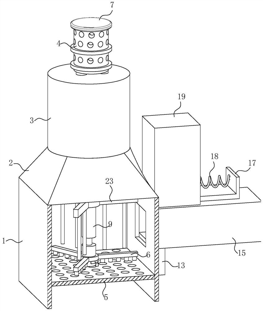
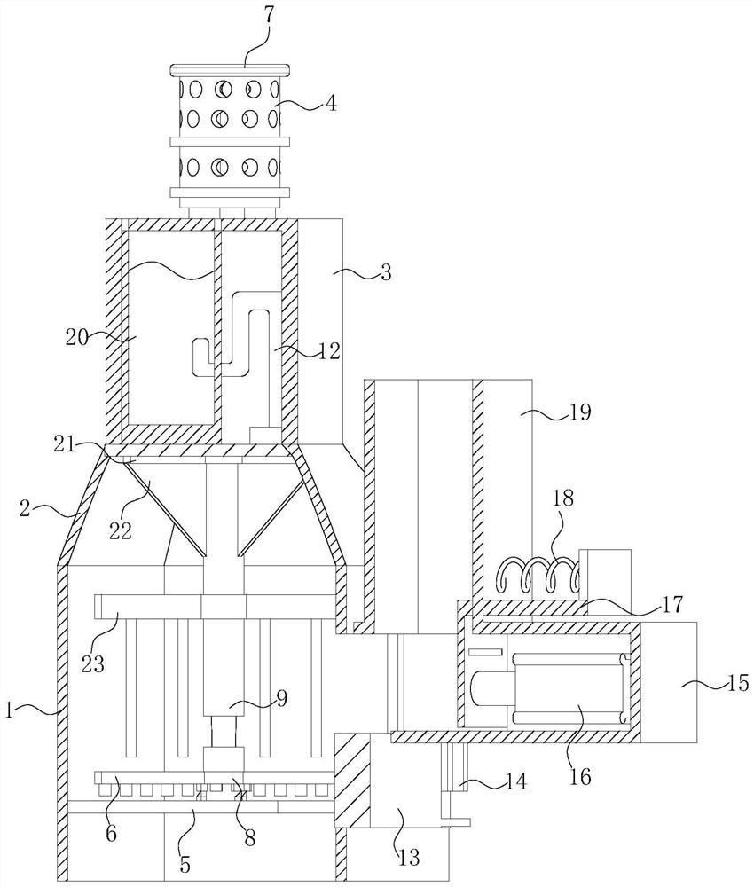
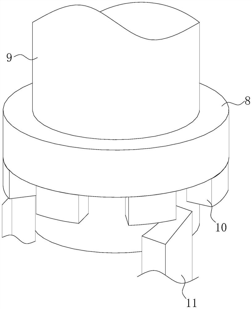
[0025] see Figure 1-4 , the present invention provides a technical solution: a garbage disposal device, comprising a combustion furnace 1, a gas guide table 2 is fixedly connected to the upper end of the combustion furnace 1, and a purification cylinder 3 is fixedly connected to the upper end of the gas guide table 2, The upper end of the purification cylinder 3 is fixedly connected with a releaser 4; the lower end of the combustion furnace 1 is fixedly connected with a partition plate 5, and the partition plate 5 is overlapped with a plurality of through-hole strips 6 distributed in a circular array. Each of the through-hole bars 6 is fixedly connected with a fixing ring 8 , and the fixing ring 8 is fixedly connected with a telescopic rotating shaft 9 , and a stirring rod 23 is fixedly connected to the telescopic rotating shaft 9 , and a turbine is fixedly connected to the telescopic rotating shaft 9 Leaf 22, the upper end of the telescopic shaft 9 is rotatably connected to ...


PUM


Abstract

The invention discloses a garbage treatment device and method in the technical field of garbage treatment.The garbage treatment device comprises a combustion furnace, the upper end of the combustion furnace is fixedly connected with a gas guide table, the upper end of the gas guide table is fixedly connected with a purification barrel, and the upper end of the purification barrel is fixedly connected with a releaser; a partition plate is fixedly connected to the lower end of the combustion furnace, a plurality of through hole strips distributed in a circumferential array are connected to the partition plate in a lap joint mode, and the through hole strips are jointly and fixedly connected with a fixing ring. When the fixing block leaves the inclined surface of the first wedge-shaped block, the fixing block, the telescopic rotating shaft and the fixing ring fall, and at the moment, the through hole strip on the fixing ring falls to act on the partition plate; when the partition plate vibrates to vibrate ash on the leakage holes to dredge the leakage holes, the through hole blocks on the through hole strips extrude the ash accumulated on the leakage holes of the partition plate to further dredge the leakage holes, and the partition plate can better leak the ash out.

Description

technical field [0001] The invention relates to the technical field of garbage disposal, in particular to a garbage disposal device and method. Background technique [0002] The amount of municipal solid waste generated every year has doubled; the traditional way of garbage disposal is to build a landfill and land the garbage; this method has many drawbacks, such as occupying a lot of land to build a landfill, a large amount of organic matter and batteries The toxic filtrate produced by the landfill of other substances will cause serious pollution to soil and groundwater. A large amount of waste gas is generated and discharged into the atmosphere. Most of the existing waste gas treatment in the combustion furnace is to install a spray device at the gas outlet to spray the purified water on the waste gas, but the use of spray is actually a lot of small water droplets. The exhaust gas is sprayed out, and the exhaust gas is in a gaseous state. The spraying method cannot comple...

Claims


Application Information

Patent Timeline
Patent Type & Authority Applications(China)
IPC IPC(8): F23G5/24F23G5/28F23G5/44F23J1/06F23J15/00F23J15/04F01K25/14
CPCF23G5/28F23G5/245F23G5/444F23J15/04F23J15/006F23J1/06F01K25/14
Inventor 郭光阳
Owner 郭光阳
Why Eureka
Try Eureka