
Oil gas recovery method for tanker wharf

A recovery method and technology for oil and gas, applied in separation methods, chemical instruments and methods, recovery of liquid hydrocarbon mixtures, etc., can solve the problems of large oil and gas temperature fluctuations, large energy consumption, and large energy consumption of units, and achieve improved refrigeration energy efficiency and stability. Oil and gas temperature, the effect of ensuring continuity

Pending Publication Date: 2022-07-05
NANJING DOULE REFRIGERATION EQUIP
View PDF0 Cites 0 Cited by
  • Summary
  • Abstract
  • Description
  • Claims
  • Application Information

AI Technical Summary

Problems solved by technology

Subsequently, oil and gas recovery at crude oil terminals was steadily promoted along the coast, and more and more oil and gas recovery facilities were installed in port terminals, and the continuous operation of terminal oil and gas recovery facilities can basically meet the continuity of shipment, but the effect of use is uneven, and the energy consumption is relatively large. big
Existing technologies such as "a wharf oil and gas recovery device" (CN2013104309861) solve the problem of continuous operation of the device, but for chemical VOCs waste gas, because there is no spare cold field for deep cooling, it cannot realize continuous operation of the wharf for 24 hours
In addition, the existing oil and gas recovery facilities at the oil terminal have large oil and gas temperature fluctuations and relatively large energy consumption of the unit

Method used


Image

  • Oil gas recovery method for tanker wharf
  • Oil gas recovery method for tanker wharf
  • Oil gas recovery method for tanker wharf

Examples


Embodiment 1

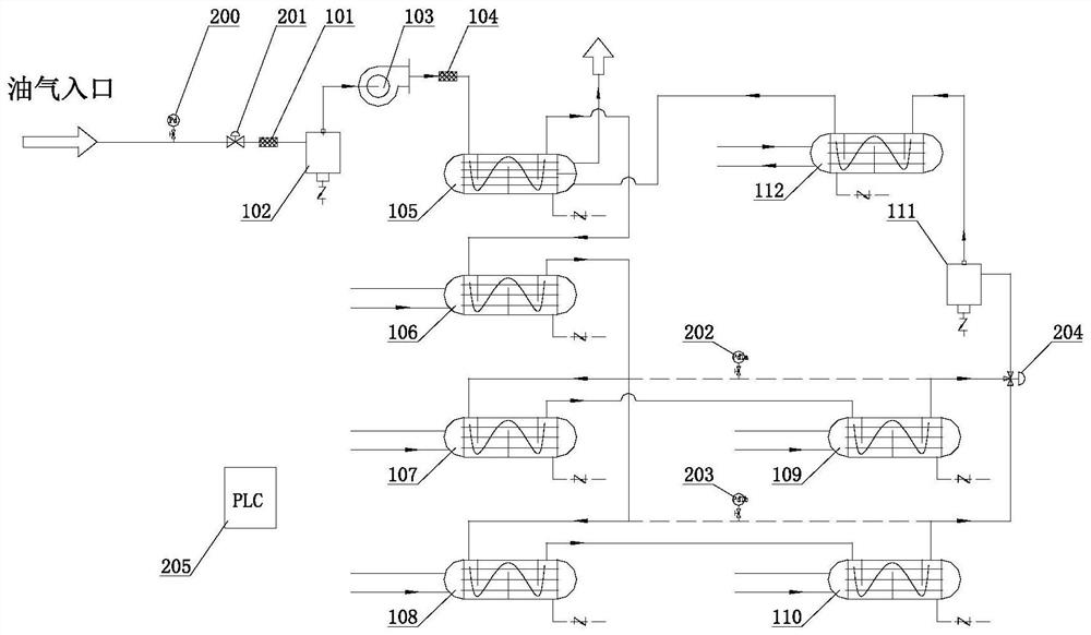
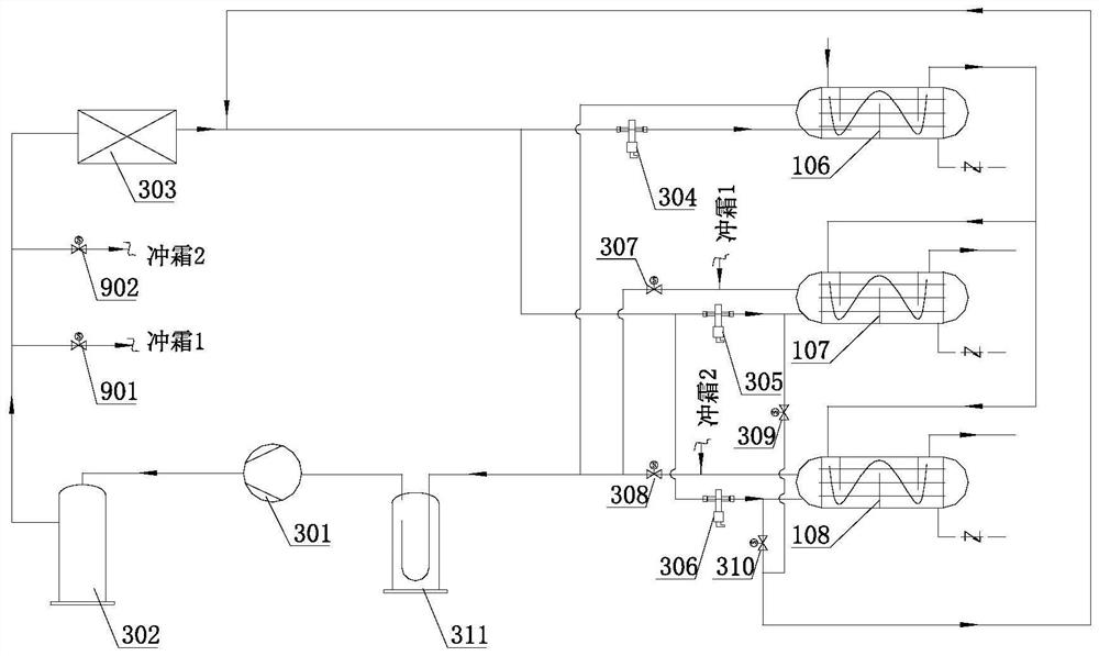
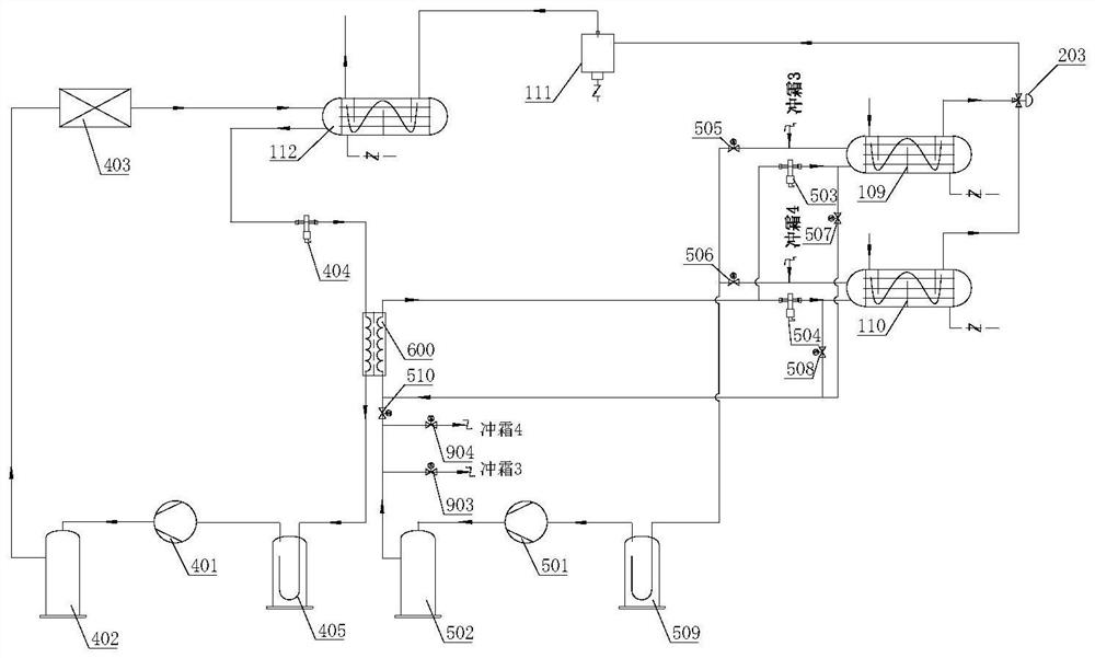
[0038] Example 1: as Figure 1-Figure 3 As shown, the oil and gas recovery method of the oil tanker terminal of the present invention comprises the following steps:

[0039] (S1) The oil and gas to be treated sent from the oil and gas inlet is sent to the oil and gas system, and passes through the regenerative heat exchanger, pre-cooling heat exchanger, shallow cooling heat exchanger, deep cooling heat exchanger and gas-fluorine exchange in the oil and gas system in turn The heat exchanger liquefies the oil and gas by exchanging heat with the refrigerant sent from the refrigeration system, and the oil and gas treated by the gas-fluorine heat exchanger is sent to the regenerative heat exchanger again, and is discharged after heat exchange in the regenerative heat exchanger;

[0040] (S2) The refrigeration system includes a primary refrigeration system, a secondary refrigeration system and a tertiary refrigeration system; the primary refrigeration system sends the refrigerant to...

Embodiment 2

[0071] Example 2: The processing capacity is 300m 3 / h Oil and gas recovery device of oil tanker terminal, oil and gas are volatile oil and gas of refined oil, and the concentration of intake air is 1000g / m 3, the current market equipped terminal oil and gas recovery device is composed of two sets of -70 ℃ single-channel condensing oil and gas recovery systems, the power of the air pump is 5.5kW, the power of the single-channel condensation system is 49.4kW, the total power of the unit is 104.3kW, and the unit energy consumption is 0.348 kW / (m 3 / h).

[0072] The invention 300m 3 / h Oil and gas recovery device at the oil tanker terminal, the final oil and gas temperature is -70℃, the air pump is Shandong Fengyuan explosion-proof Roots air pump with a power of 5.5kW, and the first-stage explosion-proof compressor of the dual-circuit condensing system is the German Bitzer piston compressor 4GE-23Y , power 14.3kW, the second-stage explosion-proof compressor is China Taiwan Fus...


PUM


Abstract

The invention discloses an oil tanker wharf oil gas recovery method, which comprises the following steps that to-be-treated oil gas fed from an oil gas inlet is fed into an oil gas system and sequentially passes through a backheating heat exchanger, a pre-cooling heat exchanger, a shallow cooling heat exchanger, a deep cooling heat exchanger and a gas-fluorine heat exchanger in the oil gas system; oil gas is liquefied through heat exchange with a refrigerant sent out by a refrigerating system, and the oil gas treated by the gas-fluorine heat exchanger is sent into the regenerative heat exchanger again and discharged after heat exchange in the regenerative heat exchanger. When the system needs to be defrosted, a high-temperature and high-pressure refrigerant is fed into the shallow cooling heat exchanger and the deep cooling heat exchanger to be defrosted. According to the invention, the cold field temperature fluctuation of the oil tanker wharf oil gas recovery device is + / -4 DEG C, and the energy efficiency is improved by more than 40%.

Description

technical field [0001] The invention belongs to the technical field of oil and gas recovery, in particular to a method for oil and gas recovery of oil tanker terminals. Background technique [0002] The construction of oil and gas recovery facilities at the terminal started late, and the actual operation experience is insufficient. Subsequently, the oil and gas recovery of crude oil terminals was steadily promoted in the coastal areas. More and more oil and gas recovery facilities were installed in port terminals, and the continuous operation of oil and gas recovery facilities at the terminals could basically meet the continuity of loading, but the use effects were uneven, and the energy consumption was relatively big. Existing technologies such as "a wharf oil and gas recovery device" (CN2013104309861) solve the problem of continuous operation of the device, but for chemical VOCs waste gas, because there is no standby cold field in cryogenic refrigeration, it cannot realiz...

Claims


Application Information

Patent Timeline
IPC IPC(8): B01D5/00C10G5/06
CPCB01D5/0051B01D5/0039B01D5/0036C10G5/06
Inventor 张林张贵德缪志华刘金波
Owner NANJING DOULE REFRIGERATION EQUIP
Learn More