Chip

A chip and main body technology, applied in the field of nucleic acid detection, can solve problems such as deterioration detection ability, decline, aerosol pollution, etc., and achieve the effect of convenient operation and improved operation efficiency.

Active Publication Date: 2022-07-05
至美时代生物智能科技(北京)有限公司 +1
View PDF8 Cites 0 Cited by
  • Summary
  • Abstract
  • Description
  • Claims
  • Application Information

AI Technical Summary

Problems solved by technology

[0004] Chips are widely used in the field of nucleic acid detection. The existing chips usually pre-embed freeze-dried detection reagents in the reaction chamber of the chip. Since there are generally multiple reaction chambers on the chip, the embedding of the detection reagents is time-consuming and laborious. It is conducive to the mass production of chips; at the same time, the freeze-dried detection reagents are easy to deteriorate due to moisture, oxidation, etc. Aerosol pollution will affect the accuracy of the next test result, so it is necessary to seal the produced chip, remove the seal of the sealed chip before using the chip, and seal the chip again before the detection reaction. The above operations need to be done manually , not easy to use in an automated detection system

Method used


Image

  • Chip
  • Chip
  • Chip

Examples


Embodiment 1

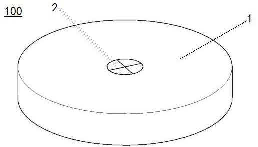
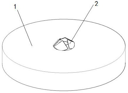
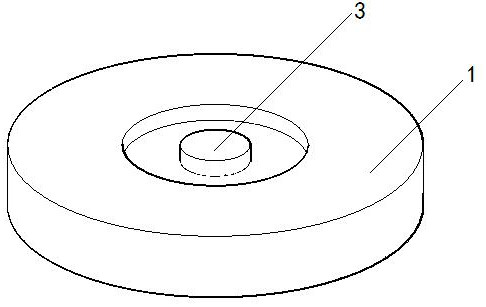
[0049] like Figure 1-Figure 11 As shown, this embodiment provides a chip 100, which is mainly used for nucleic acid detection, and includes a main body 1, a top cover 2 and a storage member 3. A through hole 17 is opened in the middle of the main body 1, and the upper end of the through hole 17 is connected to the top cover. 2 is connected by an openable sealing layer and closed by the top cover 2, a plurality of flow channels 5 are opened on the outer periphery of the through hole 17, one end of each flow channel 5 is connected to the through hole 17, and the other end of each flow channel 5 is connected to a The reaction chamber 6, the reaction chamber 6 is not communicated with the outside world, and at the same time, it cooperates with the setting of the top cover 2 to form a good sealing condition, which can prevent the detection reagent from contacting the outside for a long time before the reaction starts, and prevent the detection reagent from being oxidized, damp or p...

Embodiment 2

[0055] like Figure 12 As shown, the difference between this embodiment and the first embodiment is that the outer wall of the base 11 is provided with a ring of accommodating grooves, and the accommodating groove is used to embed the bottom sealing ring 12, and the outer diameter of the bottom sealing ring 12 is equal to the outer diameter of the base 11, In addition, the outer wall of the bottom sealing ring 12 is in contact with the inner wall of the through hole 17, so that the sealing effect can be improved through the bottom sealing ring 12, and the detection reagent in the storage part 3 can be prevented from deteriorating due to moisture and oxidation. The bottom sealing ring 12 can be made of rubber material. .

Embodiment 3

[0057] like Figures 13-14 As shown, the difference between this embodiment and the second embodiment is that a limit groove 18 is provided on one side of the groove 4, a limit rod 19 is fixed on the outer edge of the base 11, and the lower bottom surface of the limit rod 19 and the bottom surface of the base 11 are fixed. On the same horizontal plane, the end of the limit rod 19 away from the base 11 can extend into the limit groove 18, and the width of the limit rod 19 is equal to the width of the limit groove 18, and the limit rod 19 is positioned at the upper limit in the horizontal direction to ensure that the limit rod 19 can only reciprocate in the vertical direction, thereby preventing the rotation of the storage member 3 relative to the through hole 17, affecting the alignment of the flow channel 5 and the liquid inlet hole 7, and the position of the limit groove 18. The depth is equal to the sum of the height of the limit rod 19 and the depth of the groove 4 . When t...


PUM


Abstract

The upper end of a through hole in the middle of a main body is connected with a top cover through a sealing layer capable of being opened, a plurality of flow channels are formed in the periphery of the through hole, the two ends of each flow channel are communicated with the through hole and a reaction chamber respectively, a storage part is hollow, a protruding part is arranged at the upper end of the storage part, and a sample adding opening is formed in the upper end of the protruding part; a plurality of liquid inlet holes are formed in the lower portion of the side wall of the storage part, the storage part is located in the through hole, the top cover blocks the upper end of the through hole before detection, part of the outer wall of the storage part is in transition fit with the inner wall of the through hole, the liquid inlet holes can be blocked through the inner wall of the through hole, and the storage part can move upwards along the through hole to eject the top cover open and is in a communicated state. In the communication state, a to-be-detected sample can be added into the storage part through the sample adding opening, the liquid inlet hole is communicated with the flow channel, and the to-be-detected sample and the detection reagent in the storage part can flow into the reaction chamber through the flow channel to react. The chip has a good sealed storage condition, and is high in detection precision, simple to operate and suitable for automatic detection.

Description

technical field [0001] The present invention relates to the technical field of nucleic acid detection, in particular to a chip. Background technique [0002] Microfluidics, also known as microfluidic chip technology, can integrate basic operation units such as sample preparation, reaction, separation, and detection in biological, chemical, and medical analysis processes into a chip of several square centimeters to control Fluids run through the entire system to replace various functions of conventional chemical or biological laboratories. It has the advantages of light weight, small amount of samples and reagents, low energy consumption, fast reaction speed, parallel processing in large quantities, and disposables. At present, microfluidics has great development potential and broad application prospects in biomedical research (such as nucleic acid detection). [0003] Aerosol refers to a gaseous dispersion system composed of solid or liquid particles suspended in a gas medi...

Claims


Application Information

Patent Timeline
Patent Type & Authority Applications(China)
IPC IPC(8): B01L3/00
CPCB01L3/5027B01L2300/0832
Inventor 不公告发明人
Owner 至美时代生物智能科技(北京)有限公司
Why Eureka
Try Eureka