
Perforating device for processing fuel filter

A technology of fuel filter and drilling device, which is applied in the direction of positioning device, metal processing equipment, metal processing machinery parts, etc., and can solve the problem that the adjustment, clamp cannot be in multiple positions, and cannot meet the requirements of filter housing drilling and other problems, to achieve the effect of uniform punching distribution and fast switching

Pending Publication Date: 2022-07-05
ZHEJIANG SHENGFENG AUTO PARTS
View PDF0 Cites 0 Cited by
  • Summary
  • Abstract
  • Description
  • Claims
  • Application Information

AI Technical Summary

Problems solved by technology

[0003] The fuel filter is composed of an inner filter element and an outer shell. When installing the shell, holes need to be drilled on the surface to facilitate installation. The installation through hole of the shell is a large hole in the middle and several holes around the A small hole is formed together, while the traditional punching machine can only punch through holes of different sizes on the shell by changing the drill bit back and forth, and the position of the drill bit remains unchanged. At this time, it is necessary to continuously adjust the position of the shell fixture. position to work on several small holes in the periphery, but the existing fixture cannot adjust multiple positions, so it cannot meet the drilling requirements of the filter housing

Method used


Image

  • Perforating device for processing fuel filter
  • Perforating device for processing fuel filter
  • Perforating device for processing fuel filter

Examples


Embodiment Construction

[0025] The technical solutions in the embodiments of the present invention will be clearly and completely described below with reference to the accompanying drawings in the embodiments of the present invention. Obviously, the described embodiments are only a part of the embodiments of the present invention, but not all of the embodiments. Based on the embodiments of the present invention, all other embodiments obtained by those of ordinary skill in the art without creative efforts shall fall within the protection scope of the present invention.

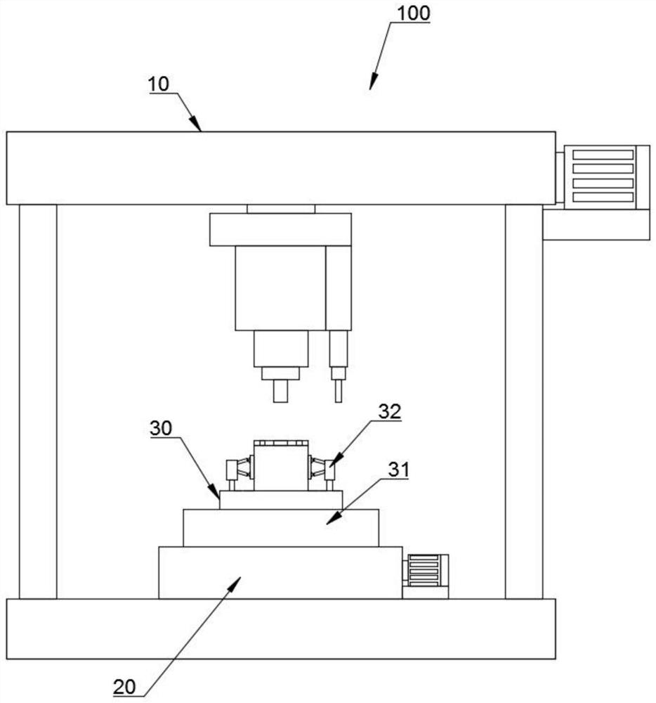
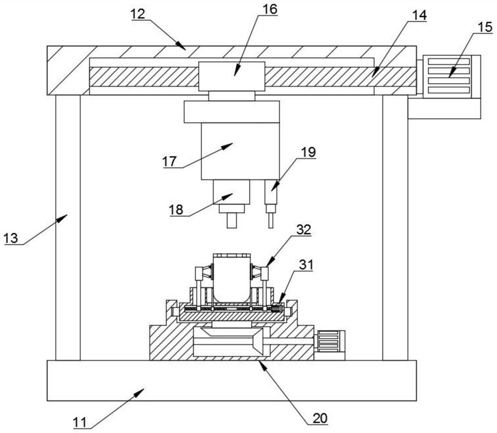
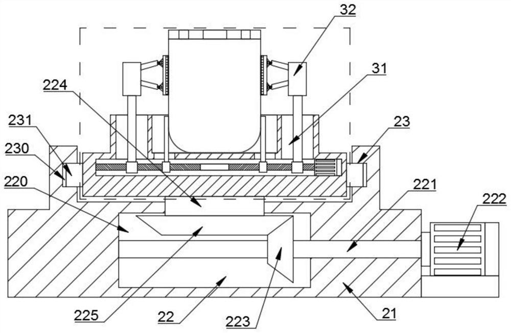
[0026] like Figure 1 to Figure 5 As shown, in the embodiment of the present invention, a punching device 100 for processing a fuel filter is characterized in that it includes: a filter housing punching mechanism 10, a position adjusting mechanism 20 and a clamping and fixing mechanism 30. The position adjusting mechanism 20 is disposed below the filter housing punching mechanism 10 for transferring the position of the clamping and fi...


PUM


Abstract

The invention relates to a punching device for fuel filter machining. The punching device comprises a filter shell punching mechanism, a position adjusting mechanism and a clamping and fixing mechanism. The filter shell punching mechanism comprises a mounting base, an adjusting top plate, a side supporting column, a driving screw rod, a first driving motor, a driving screw sleeve, a punching driver, a large-hole drill bit and a small-hole drill bit. And the adjusting top plate is arranged above the mounting base. The side supporting columns are used for supporting and fixing the adjusting top plate. And the driving screw rod is rotationally arranged in the bin of the adjusting top plate. The end of the driving screw penetrates out of the adjusting top plate inner bin. The drilling tool has the beneficial effect that the drilling tool can be matched with the clamp by changing the position of the drill bit. And deviation adjustment is conducted on the fixed position of the filter shell through the rotating clamp to be matched with the drill bit. Therefore, the holes in the middle of the top end of the filter shell and the small holes distributed in the side edge of the middle are punched more uniformly.

Description

technical field [0001] The invention relates to the technical field of fuel filters, in particular to a punching device for processing fuel filters. Background technique [0002] There are three types of fuel filters: diesel filters, gasoline filters and natural gas filters. The function of the fuel filter is to prevent particulate matter, water and impurities in the fuel, and to ensure that the precise components of the fuel system are protected from wear and other damage. The fuel filter is connected in series on the pipeline between the fuel pump and the throttle body inlet. The function of the fuel filter is to remove solid impurities such as iron oxide and dust contained in the fuel to prevent the fuel system from being blocked (especially the fuel injector). Reduce mechanical wear, ensure stable engine operation and improve reliability. The structure of the fuel burner consists of an aluminum shell and a bracket with stainless steel inside. The support is equipped ...

Claims


Application Information

Patent Timeline
Patent Type & Authority Applications(China)
IPC IPC(8): B23B41/00B23B39/16B23B39/14B23B47/00B23Q3/06
CPCB23B41/00B23B39/16B23B39/14B23B47/00B23Q3/062
Inventor 戴圣亮叶挺潞李焕海
Owner ZHEJIANG SHENGFENG AUTO PARTS
Learn More