High-temperature-resistant copper bar injection mold and process for three-electric product of new energy automobile

A technology of new energy vehicles and injection molds, which is applied to household appliances, other household appliances, applications, etc., can solve problems such as low sealing efficiency, high maintenance cost, and insufficient sealing, and achieve reduced production costs and production cycles. The row structure is simple and realizes the effect of copper row assembly

Pending Publication Date: 2022-07-05
JIANGSU AOLIWEI SENSING TECH
View PDF4 Cites 0 Cited by
  • Summary
  • Abstract
  • Description
  • Claims
  • Application Information

AI Technical Summary

Problems solved by technology

[0003] Aiming at the deficiencies in the prior art, the present invention provides a high-temperature-resistant copper bar injection mold and process for new energy automobile three-electric products, which solves the problem of the existing copper bar injection molded parts due to the different specific heat of metal poles and plastics. The problem of insufficient sealing, solve the problem of high maintenance cost, and solve the problem of low efficiency of sealing

Method used


Image

  • High-temperature-resistant copper bar injection mold and process for three-electric product of new energy automobile
  • High-temperature-resistant copper bar injection mold and process for three-electric product of new energy automobile
  • High-temperature-resistant copper bar injection mold and process for three-electric product of new energy automobile

Examples


Embodiment Construction

[0030] The technical solutions in the embodiments of the present invention will be clearly and completely described below with reference to the accompanying drawings in the embodiments of the present invention. Obviously, the described embodiments are only a part of the embodiments of the present invention, rather than all the embodiments. Based on the embodiments of the present invention, all other embodiments obtained by those of ordinary skill in the art without creative efforts shall fall within the protection scope of the present invention.

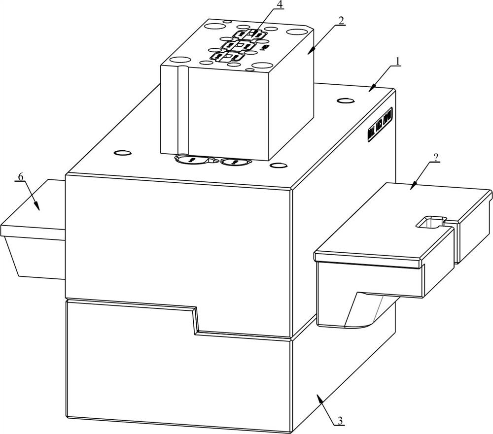
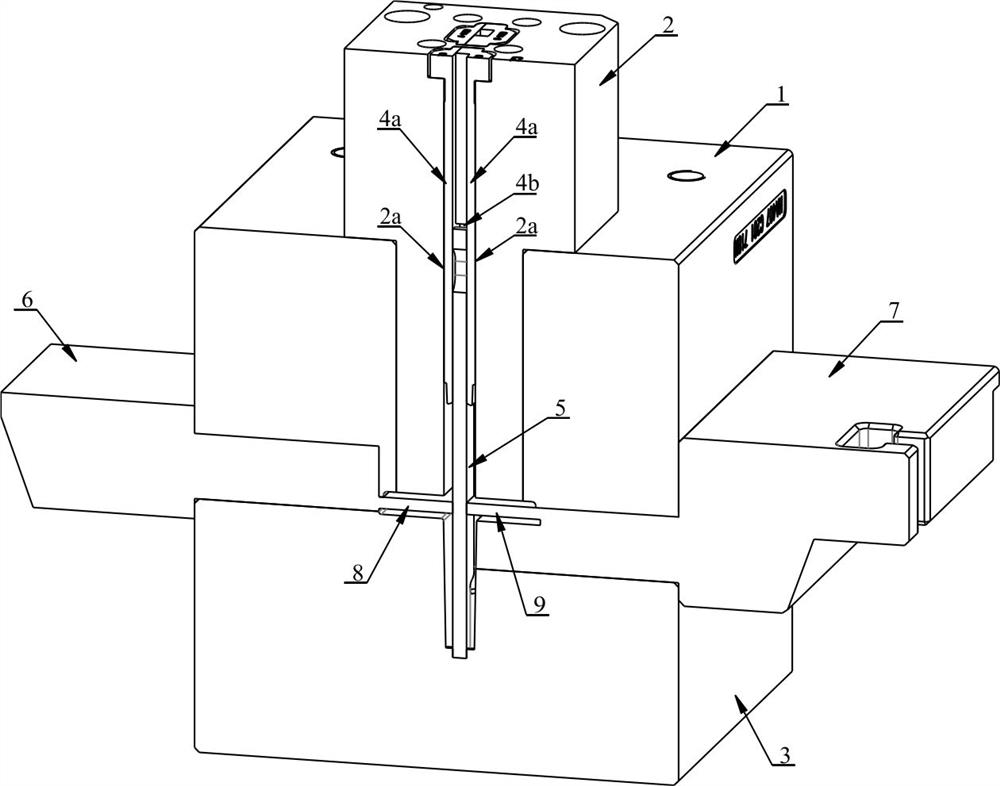
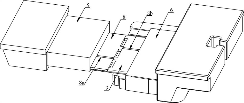
[0031] like Figure 1-4 The shown injection mold for high temperature resistant copper bars for three electric products of new energy vehicles includes a first upper mold 1 and a lower mold 3, and a first jack is opened in the middle of the first upper mold 1, and the jack is inserted into the hole. There is a second upper die 2, which is fixed on the first upper die 1 by screws. The center of the second upper die 2 is provided with ...


PUM


Abstract

The high-temperature-resistant copper bar injection mold comprises a first upper mold body and a lower mold body, a first inserting hole is formed in the middle of the first upper mold body, a second upper mold body is inserted into the inserting hole, a second inserting hole is formed in the center of the second upper mold body, and a clamp used for clamping a copper bar is inserted into the second inserting hole; an injection mold cavity is formed among the first upper mold, the second upper mold, the lower mold and the clamp, a first sliding block and a second sliding block which are inserted from a splicing face are arranged on the two sides of the first upper mold and the two sides of the lower mold, a first inserting plate which is inserted into the mold cavity and abuts against a copper bar is arranged at the end of the first sliding block, and a second inserting plate which is inserted into the mold cavity and abuts against the copper bar is arranged at the end of the second sliding block. The first inserting plate and the second inserting plate are symmetrically arranged on the two sides of the copper bar and divide the mold cavity into an upper half part and a lower half part, the mold further comprises a third sliding block and a fourth sliding block which replace the first sliding block and the second sliding block, no inserting plate is arranged at the end of the third sliding block and the end of the fourth sliding block, and the manufactured copper bar injection molding part permanently solves the leakage risk of a product.

Description

technical field [0001] The invention relates to the technical field of copper bar injection molding, in particular to a copper bar injection mold and a process. Background technique [0002] At present, the conductive connection copper bars on the market are mostly single-insert injection molding structures. This structure meets the requirements for electrical products without sealing requirements. The tightness between the upper and lower halves of the row, that is, the inner and outer structure of the injection-molded copper row, the two ends of the copper row are connected to the motor and the electronic controller respectively, the motor is in a sealed sealed cavity, and the cavity has power supply The oil cooled by the machine, the electronic control part has IGBT modules, PCB boards and capacitors and other devices, which cannot be in contact with the liquid). The sealing outside the injection molding structure of the insert is easy to ensure, but due to the single met...

Claims


Application Information

Patent Timeline
Patent Type & Authority Applications(China)
IPC IPC(8): B29C45/33B29C45/14B29L31/36
CPCB29C45/33B29C45/14B29C45/14065B29L2031/36
Inventor 刘双全李涛高计超
Owner JIANGSU AOLIWEI SENSING TECH
Why Eureka
Try Eureka