
Automatic implanting machine

An implanting machine, automatic technology, applied in the direction of vibrating conveyor, conveyor, conveyor object, etc., can solve the problems of high labor intensity, high labor cost, low efficiency, etc., to improve work efficiency, reduce labor intensity and labor cost. Effect

Pending Publication Date: 2022-07-05
格特微智能科技(厦门)有限公司
View PDF0 Cites 0 Cited by
  • Summary
  • Abstract
  • Description
  • Claims
  • Application Information

AI Technical Summary

Problems solved by technology

[0003] However, in the prior art, manual operations are often used to implant capacitors into the receiving holes of the implanted board. Pour a pile of capacitors into the implanted board, then scrape or shake the capacitors evenly, and then scrape the excess capacitors back into the material. In the frame, this manual implantation method is labor-intensive and inefficient, and in order to meet the mass production and keep up with the production progress, it often requires multiple people to operate, and the labor cost is high.

Method used


Image

  • Automatic implanting machine
  • Automatic implanting machine
  • Automatic implanting machine

Examples


Embodiment Construction

[0117] In the description of the invention, it should be understood that the description indicating the orientation or positional relationship is based on the orientation or positional relationship shown in the accompanying drawings, which is only for the convenience of describing the invention and simplifying the description, rather than indicating or implying the referred device. Or the elements must have a specific orientation, be constructed and operated in a specific orientation, and therefore should not be construed as limiting the protection scope of the invention.

[0118]In the description of the invention, it should be noted that the terms "arranged", "connected" and "connected" should be understood in a broad sense, unless otherwise expressly specified and limited, for example, it may be a fixed connection or a detachable connection , or integrally connected; it can be a mechanical connection or an electrical connection; it can be a direct connection, or an indirect ...


PUM


Abstract

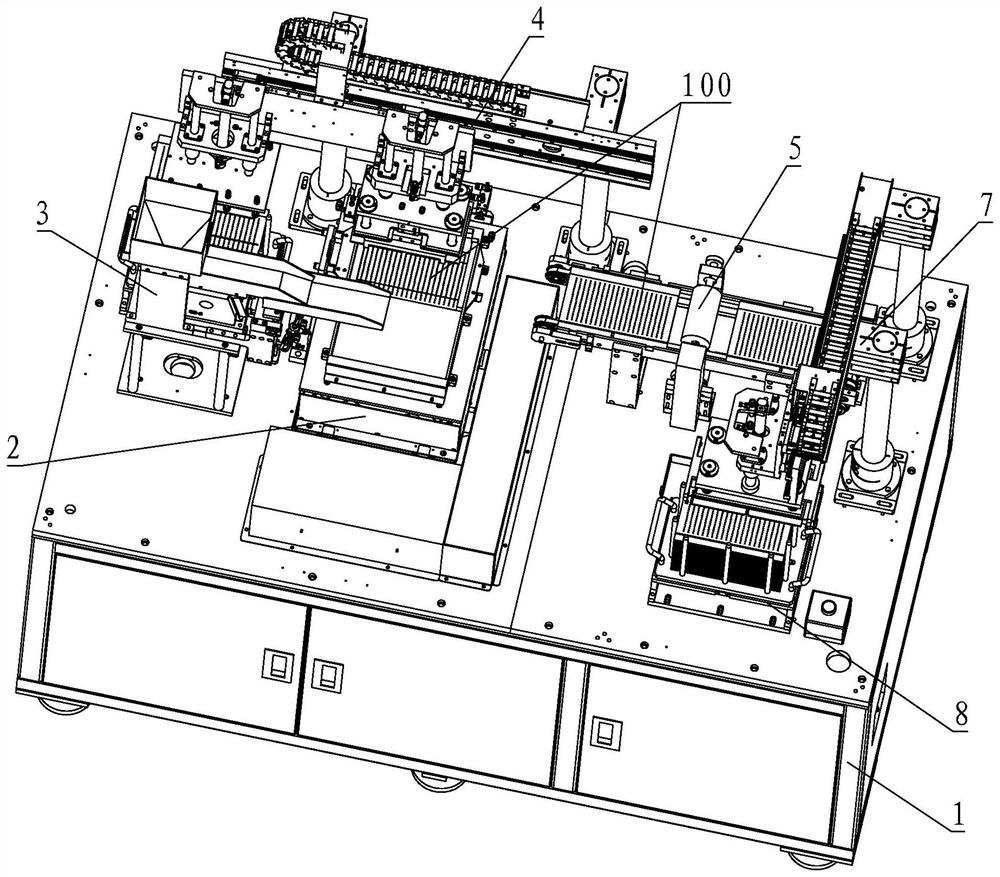
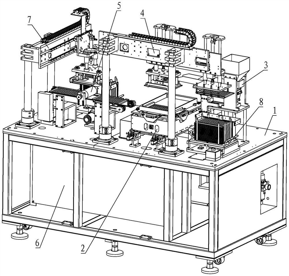
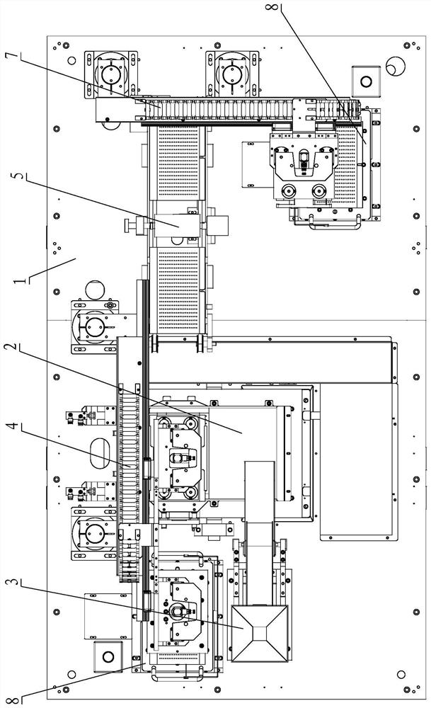
The invention provides an automatic implanting machine. The automatic implanting machine comprises a rack; the implanting mechanism comprises a vibrating disc, a first vibrating mechanism, a clamping mechanism and a swinging mechanism; a containing cavity is formed in the vibration disc in a surrounding mode, the vibration disc is further provided with an implantation plate containing groove, the implantation plate containing groove is communicated with the containing cavity, and after an implantation plate is arranged in the implantation plate containing groove, the top face of the implantation plate is flush with the bottom face of the containing cavity; the clamping mechanism is connected to the vibration disc and is used for clamping the implantation plate in the implantation plate accommodating groove; the vibration disc is connected to the first vibration mechanism; the first vibration mechanism is connected to the swing mechanism; a feeding mechanism; a first grabbing mechanism; an excess material cleaning mechanism; and a control device. The control device controls the first vibration mechanism to automatically implant the to-be-implanted product conveyed by the feeding mechanism into the implantation plate, and automatic implantation is realized, so that the working efficiency is improved, and the labor intensity and the labor cost are reduced.

Description

technical field [0001] The invention relates to the technical field of implantation of electronic components, in particular to an automatic implantation machine. Background technique [0002] In the electronics industry, capacitors need to be tested for performance after being manufactured to screen out qualified products. In the prior art, in order to improve efficiency, capacitors are usually placed in an implanted mold, such as an implanted plate. There are several rows of accommodating holes on the implant board, each row has multiple accommodating holes, and the capacitors are placed in the accommodating holes one by one. After the board is implanted with full capacitors, the whole plate is taken for testing, and the testing institutions are tested row by row to improve efficiency. [0003] In the prior art, manual operation is often used to implant capacitors into the accommodating holes of the implanted board. Pour a bunch of capacitors into the implanted board, the...

Claims


Application Information

Patent Timeline
Patent Type & Authority Applications(China)
IPC IPC(8): B65G47/52B65G47/18B65G47/24B65G47/82B65G47/91B65G27/04B65G43/10B65G43/08B07C5/02
CPCB65G47/52B65G47/18B65G47/24B65G47/82B65G47/91B65G27/04B65G43/10B65G43/08B07C5/02Y02P70/50
Inventor 罗光裕
Owner 格特微智能科技(厦门)有限公司
Learn More