Multi-driving-shaft-system water-carrying detection robot
A multi-drive, robot technology, applied in the field of inspection, can solve the problems of poor adaptability and the inability of pipeline inspection robots to adapt to the complex and changeable environment of the pipeline, achieve strong adaptability, improve the detection ability with water or full water, and expand the scope of application and scene effects
- Summary
- Abstract
- Description
- Claims
- Application Information
AI Technical Summary
Problems solved by technology
Method used
Image

Examples
Embodiment 1
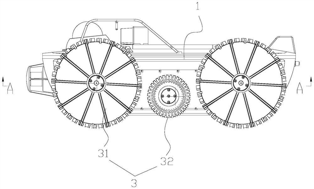
[0058] like figure 1 , Figure 7 , Figure 10 As shown, the multi-drive shaft belt water detection robot includes a vehicle body assembly 1, a drive assembly 2, and a wheel assembly 3; the drive assembly 2 is connected to the vehicle body assembly 1, and the drive assembly The driving end of 2 is detachably connected to the wheel assembly 3 after extending out of the vehicle body assembly 1 .
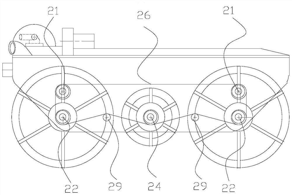
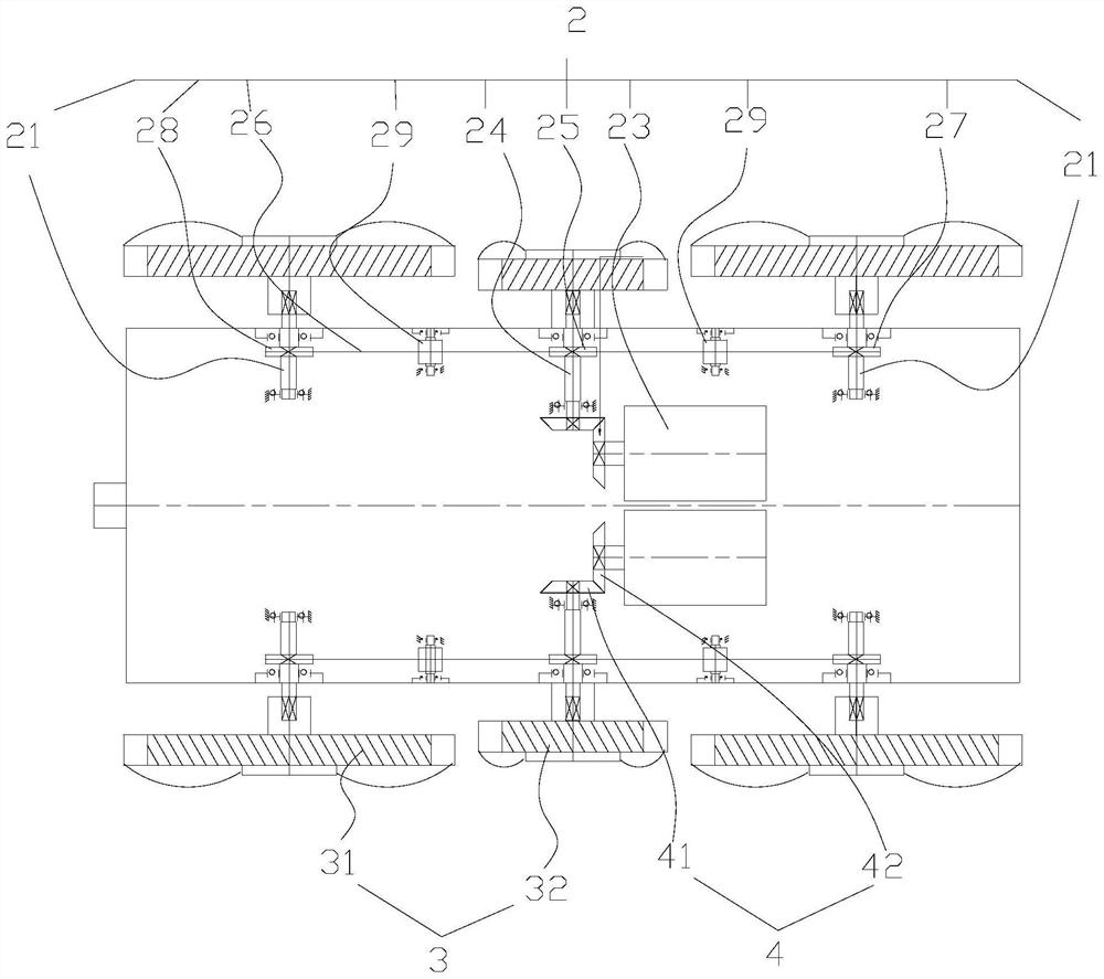
[0059] Specifically, as figure 2 , image 3 , Figure 4 As shown, one side of the drive assembly 2 includes a first drive shaft 21, a second drive shaft 22, a drive motor 23, a drive shaft 24, a drive pulley 25, a flexible transmission belt 26, a first driven pulley 27, a second driven pulley 27, and a second driven pulley 25. The driving wheel 28 and the tensioning wheel 29; the drive assembly 2 is a symmetrical structure, and a drive motor 23 drives the wheels on one side to rotate. In this embodiment, one side of the vehicle body assembly 1 includes two first drive shafts 21, t...
Embodiment 2
[0071] like Figure 13 , Figure 14 As shown, in this embodiment, on the basis of the above-mentioned first embodiment, the vehicle body assembly 1 includes a lower casing, and both sides of the lower casing include a first support wall 11 and a second support wall 12. The first support wall The wall 11 and the second support wall 12 form a accommodating cavity, and both ends of the drive shaft 24 , the first drive shaft 21 and the second drive shaft 22 are rotatably connected to the first support wall through bearings. 11 and the second support wall 12, the flexible transmission belt 26, the first driven pulley 27, the second driven pulley 28, and the tension pulley 29 are all located in the accommodating cavity.
[0072] like Figure 14 As shown, the first support wall 11 is formed by the inward depression of the lower shell of the vehicle body assembly 1 . In this embodiment, the first support wall 11 is in a rectangular boxed structure with side openings, and the second ...
Embodiment 3
[0080] like Figure 13 , Figure 16 , Figure 17 As shown, this embodiment describes the specific structures of the first wheel 31 and the second wheel 32 on the basis of the above-mentioned first or second embodiment.
[0081] like Figure 15 , Figure 16 As shown, the first wheel 31 includes a first hub 311 and a first blade 312. The first hub 311 is a flat structure with a cavity inside, and the first blades 312 are connected to the first hub 311 in a divergent shape. The outer side of the first wheel hub 311 can be formed of a metal material as the basic skeleton, wrapped with rubber on the outside, and has high strength. The first vanes 312 are circumferentially arrayed along one or both sides of the first hub 311 , the first vanes 312 may be arc-shaped or fan-shaped, and the height of the end of the first vane 312 close to the center of the circle is smaller than that of the end away from the center of the circle, the first vane 312 The rotation, in water or soft mu...
PUM
 Abstract
Description
Claims
Application Information