
Basin water environment simulation method and device

A simulation method and water environment technology, applied in the field of water environment simulation, can solve problems such as limited number of coupling boundary points, exaggerated pollutant load at boundary points, and inability to guarantee flux conservation, etc.

Pending Publication Date: 2022-07-05
TSINGHUA UNIV
View PDF0 Cites 2 Cited by
  • Summary
  • Abstract
  • Description
  • Claims
  • Application Information

AI Technical Summary

Problems solved by technology

However, the number of coupling boundary points of this method is limited, and the coupling boundary points do not change with the fluctuation of the water level of rivers, lakes and reservoirs, and the flow and pollutant load of boundary points may be exaggerated.
In the internal coupling, the land model and the water body model run synchronously in time, the results of the land model provide boundary conditions for the water body model, and the results of the water body model affect the simulation of the land model through the boundary conditions, so as to realize the dynamic two-way between the land model and the water body model coupling, but because the coupling boundary of the internal coupling mode is fixed, when the land model does not match the grid of the water body model, the water level, flow, and pollutant variables on the fixed coupling boundary point need to be realized by interpolation, which cannot be guaranteed to pass the coupling boundary The flux conservation of

Method used


Image

  • Basin water environment simulation method and device
  • Basin water environment simulation method and device
  • Basin water environment simulation method and device

Examples


Embodiment 1

[0160] like Figure 2 to Figure 14 It is shown in common that before simulating the water environment, the hydrological data of the watershed is measured or collected by instruments, and the topographic data of the mountain watershed, the data of land use types, the data of rainfall process and the related data of pollutant calculation are collected. The specific calculation process is as follows:

[0161] 1) Grid discretization and conventional parameter assignment. Based on a structured grid, the computing area is divided into a uniform rectangular grid. Figure 4 Defines the relationship between grid boundaries and adjacent grids, (i, j) is the current control volume number (or unit grid number), (i-1, j), (i+1, j) is the current unit grid Cell grids adjacent to the left and right (L, R) sides of the x-direction, (i,j-1), (i,j+1) are the top and bottom (UP, DN) of the current cell in the y-direction unit. Variables are stored at the center of the cell. Set initial cond...


PUM


Abstract

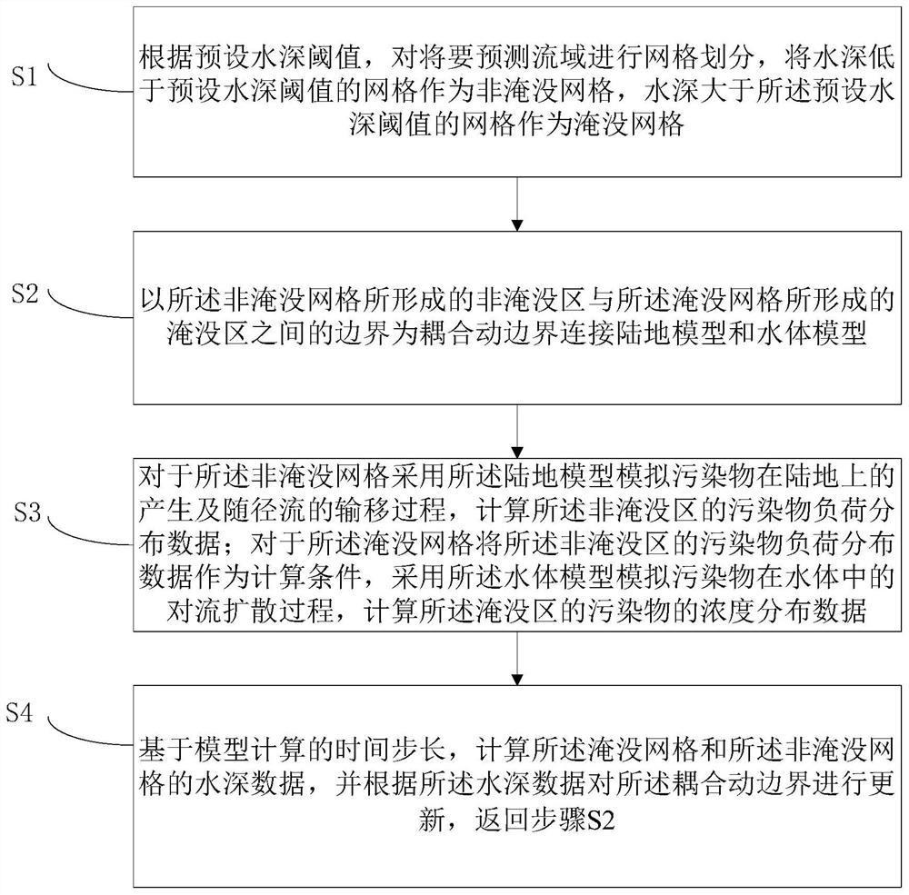
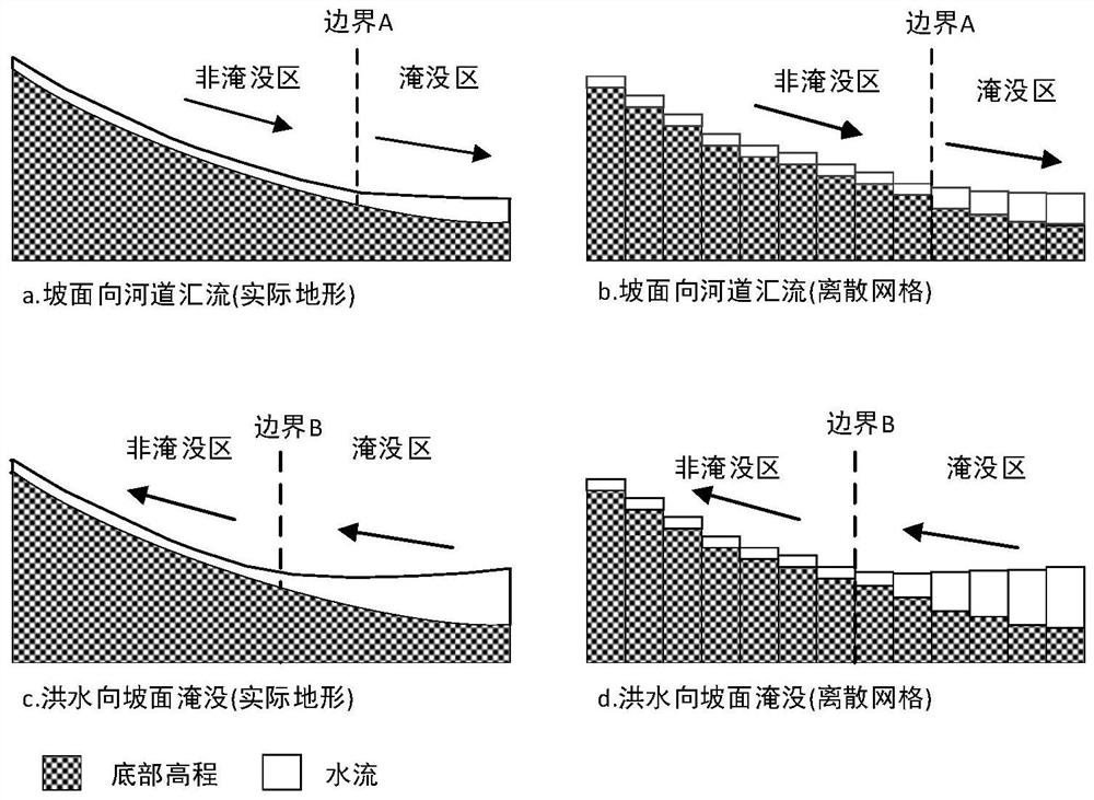
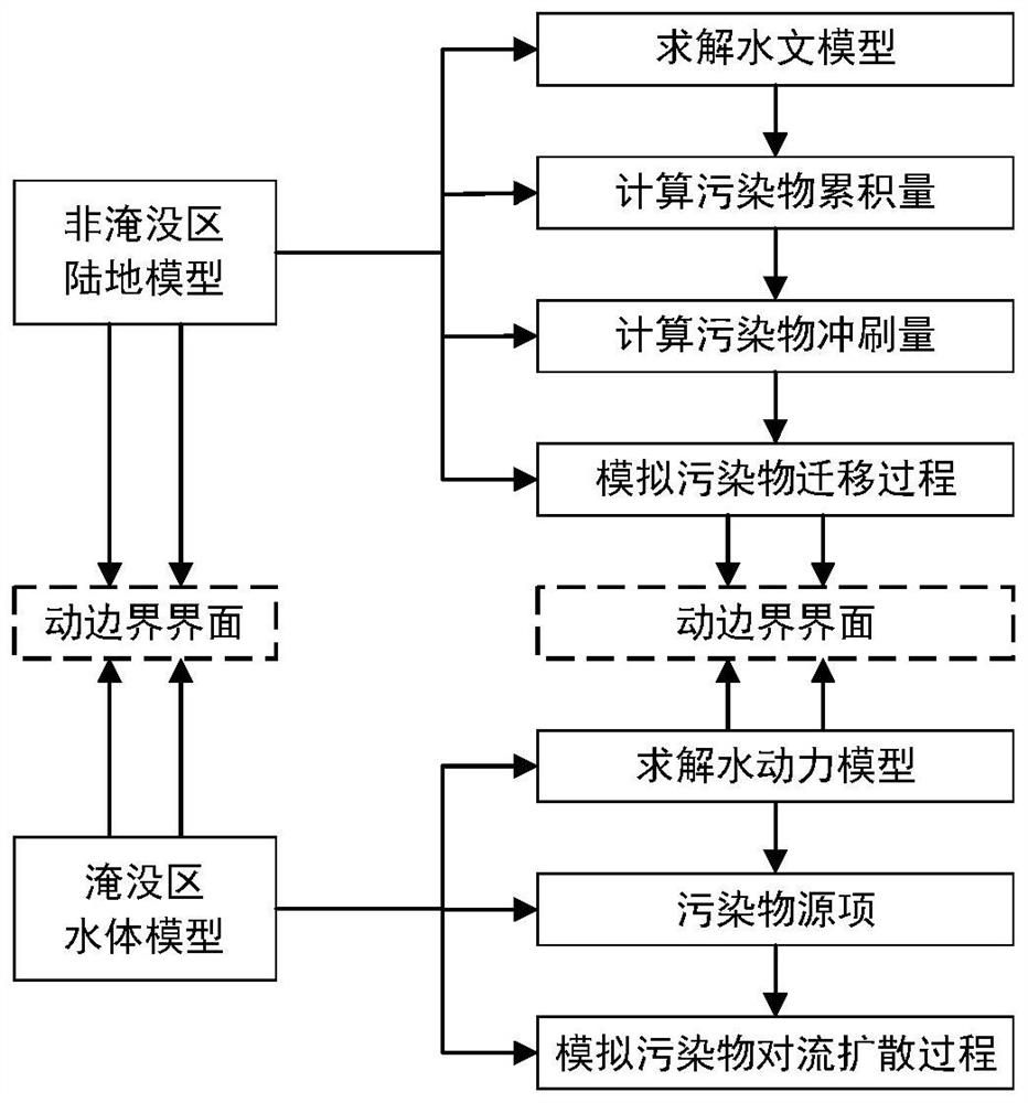
The invention provides a drainage basin water environment simulation method and device, and the method comprises the following steps: carrying out the grid division of a to-be-predicted drainage basin according to a preset water depth threshold value, taking a grid with the water depth lower than the preset water depth threshold value as a non-submerged grid, and taking a grid with the water depth greater than the preset water depth threshold value as a submerged grid; connecting the land model and the water body model by taking a boundary between the non-submerged grid and the submerged grid as a coupling dynamic boundary; for the non-submerged grids, a land model is adopted to simulate the generation of pollutants on the land and the transportation process of the pollutants along with runoff; for the submerged grid, taking pollutant load distribution data of a non-submerged area as a calculation condition, and simulating a convective diffusion process of pollutants in a water body by adopting a water body model; and according to the water depth data, carrying out grid division on the to-be-predicted drainage basin again. The method can solve the problems that an existing water environment simulation method splits watershed water-land hydrology and water quality response processes, is not scientific enough, and is low in calculation precision.

Description

technical field [0001] The invention relates to the technical field of water environment simulation, and more particularly, to a method and device for simulating a water environment in a river basin. Background technique [0002] With the process of urbanization and rapid economic development, the problem of water pollution in my country is relatively prominent, and the problem of water pollution directly threatens people's health and life safety. The comprehensive management of water environment in the basin has been highly valued by management departments at all levels. The water environment simulation of the river basin will provide a scientific basis for the design and implementation of the water environment management plan. [0003] As an important means of basin water environment analysis and simulation, numerical model-based basin water environment simulation and its application have become a hotspot of related research. According to the different functional uses of...

Claims


Application Information

Patent Timeline
IPC IPC(8): G06F30/20
CPCG06F30/20
Inventor 申言霞江春波周琦段艳华
Owner TSINGHUA UNIV
Learn More