Control cabinet with efficient heat dissipation

A control cabinet, high-efficiency technology, applied in the direction of cooling/ventilation/heating transformation, etc., can solve the problems of short circuit of components, burnout, heat radiation to the surroundings, etc., and achieve the effect of eliminating dust accumulation

Pending Publication Date: 2022-07-05
苏州中锦科技有限公司
View PDF0 Cites 0 Cited by
  • Summary
  • Abstract
  • Description
  • Claims
  • Application Information

AI Technical Summary

Problems solved by technology

[0002] Because there are a large number of electrical equipment installed inside the control cabinet, these devices will emit a lot of heat during operation. Since the control cabinet is mostly a closed cavity, it is often difficult for the heat accumulated in the control cabinet to spread to the surroundings. To radiate out, in order to solve this problem, the current common method is to install a fan embedded in the control cabinet, and then open holes in the corresponding position, and use the convection generated by the fan to take away a large amount of heat in the control cabinet. It can reduce the temperature in the control cabinet, but a large amount of dust will accumulate in the control cabinet during long-term use, and the dust accumulated in the control cabinet will cause short circuit or even burn out of components

Method used


Image

  • Control cabinet with efficient heat dissipation
  • Control cabinet with efficient heat dissipation
  • Control cabinet with efficient heat dissipation

Examples


Embodiment Construction

[0016] In order to make the technical means, creative features, goals and effects realized by the present invention easy to understand, the technical solutions in the embodiments of the present invention will be clearly and completely described below with reference to the accompanying drawings in the embodiments of the present invention.

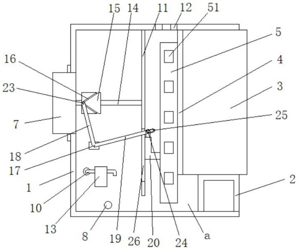
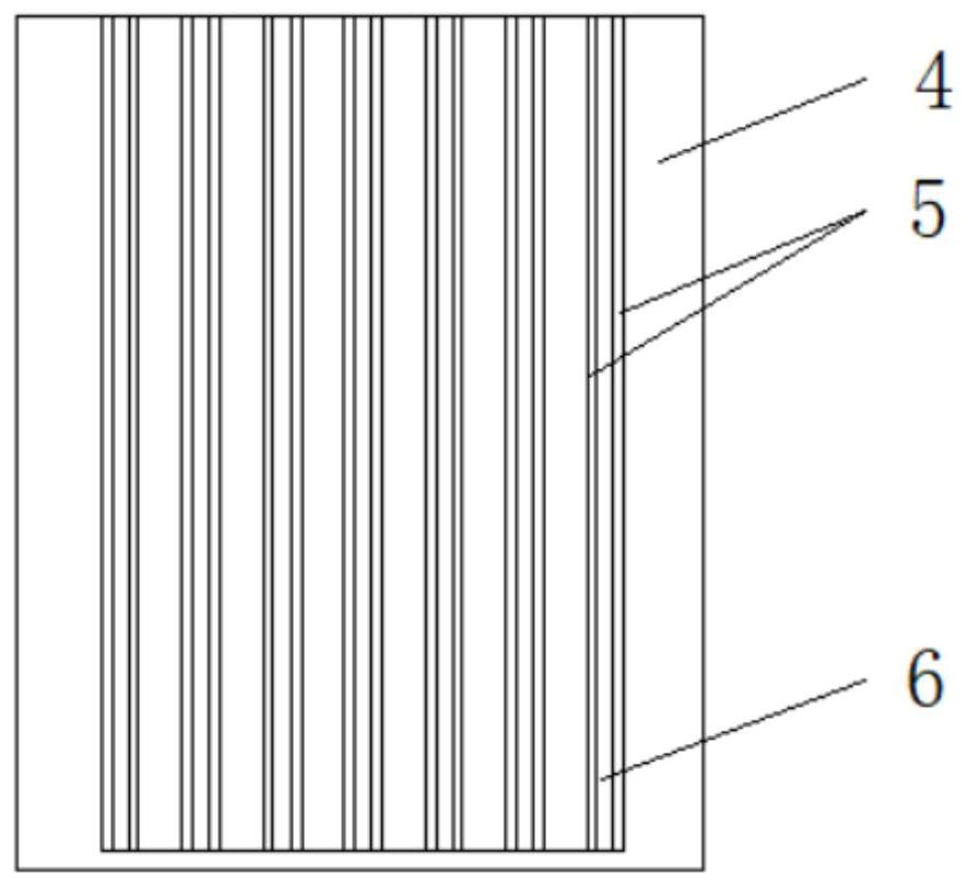
[0017] see Figure 1-3 , this specific embodiment is realized by the following technical solutions, which includes a box body 1 with an opening on one side, a step frame 2 is fixedly installed on the bottom opening side of the box body 1, and the step frame 2 is connected to the box body 1. Between the interior of the body 1 is a reservoir a, the interior of the box body 1 is provided with a control cabinet 3, the control cabinet 3 can interact with the gap between the inner wall of the box body 1 and the step frame 2, the said The back of the control cabinet 3 is a copper plate 4. The back of the copper plate 4 is provided with a number of ...


PUM


Abstract

The invention discloses an efficient heat dissipation control cabinet which comprises a box body (1) with one side provided with an opening, a step frame (2) is fixedly installed on the opening side of the bottom of the box body (1), a water storage pool (a) is arranged between the step frame (2) and the interior of the box body (1), a control cabinet body (3) is arranged in the box body (1), and the control cabinet body (3) is fixedly installed on the step frame (2). The control cabinet (3) can be in clearance interaction fit with the inner wall of the box body (1) and the step frame (2), a copper plate (4) is arranged on the back face of the control cabinet (3), a plurality of heat dissipation fins (5) are arranged on the back face of the copper plate (4), the lower ends of the heat dissipation fins (5) extend into the water storage pool (a), and a water absorption cotton strip (6) is clamped and fixed between every two adjacent heat dissipation fins (5). According to the invention, heat emitted by various components installed on the copper plate in the working process can be taken away through the cooling fins and the copper plate, the sealing effect of the control cabinet is not affected, and the phenomenon of dust accumulation is completely eradicated.

Description

technical field [0001] The invention relates to the technical field related to control cabinets, in particular to a control cabinet with efficient heat dissipation. Background technique [0002] Due to the large amount of electrical equipment installed in the control cabinet, these devices will emit a lot of heat during operation. Since the control cabinet is mostly a closed cavity, it is often difficult for the heat accumulated in the control cabinet to spread to the surrounding. Radiation out, in order to solve this problem, the current popular method is to install a fan on the control cabinet, and then open holes in the corresponding position, and use the convection generated by the fan to take away a lot of heat in the control cabinet, but this method although It can reduce the temperature in the control cabinet, but a large amount of dust will accumulate in the control cabinet during long-term use, and the dust accumulated in the control cabinet will cause short circuit...

Claims


Application Information

Patent Timeline
Patent Type & Authority Applications(China)
IPC IPC(8): H05K7/20
CPCH05K7/2039H05K7/20136H05K7/20172H05K7/20218H05K7/20272H05K7/20281
Inventor 陈联华陈晨
Owner 苏州中锦科技有限公司
Why Eureka
Try Eureka