
Blood sampling pen

A lancet and lancet technology, applied in the field of lancets, can solve the problems affecting the puncture accuracy of the lancet, the jitter of the movement line, the deviation, the deviation of the ejection line of the shooting rod, etc., so as to avoid secondary blood collection and ensure the accurate puncture. degree, the effect of reducing accidental injury

Pending Publication Date: 2022-07-08
아이센스(장쑤) 컴퍼니 리미티드
View PDF0 Cites 0 Cited by
  • Summary
  • Abstract
  • Description
  • Claims
  • Application Information

AI Technical Summary

Problems solved by technology

Normally, the blood collection pen consists of a casing, a pen cap, a shooter, a shooter spring, a needle holder, a tail handle, a button, etc. The blood collection needle is inserted into the needle holder of the shooter, and when the tail handle is pulled, the shooter compresses the shooter spring Enter the firing state and aim at the blood collection site, press the firing button, the shooting rod is fired to drive the blood collection needle to pierce; due to the guide gap between the shooting rod and the shell, there is a certain vibration and deviation in the movement line of the blood collection needle when it is shot, and it is possible There is a secondary thrust, so that the user feels increased pain
In addition, there is also the sleeve between the shooting rod and the needle seat. After repeated installation and removal of the blood collection device for many times, the injection line of the shooting rod is offset, which affects the puncture accuracy of the blood collection needle and causes the problem of increased tingling sensation on the human body.

Method used


Image

  • Blood sampling pen
  • Blood sampling pen
  • Blood sampling pen

Examples


Embodiment Construction

[0042] The present invention will be further described with reference to the accompanying drawings.

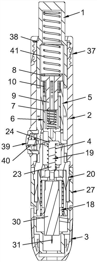
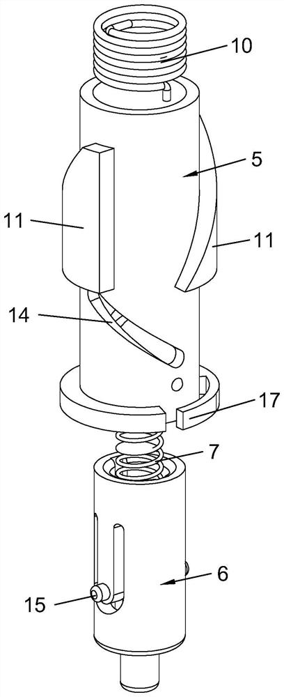
[0043] This embodiment discloses a lancing pen, such as Figures 1 to 14As shown, it includes a pressing cap 1, a pen shell 2 and a pen cap 3, and the front end of the pen cap 3 is provided with a needle outlet; the pen cap 3 is slidably provided with a blood collection needle, and a blood collection needle is also installed in the blood collection pen to cause the blood collection needle to move and reset relative to the pen cap 3. The first elastic member 4; the pen housing 2 is provided with a drive assembly for driving the blood collection needle to move downward; the drive assembly includes a rotating shaft 5 and a shooting rod 6 that is penetrated in the rotating shaft 5, and the shooting rod 6 is provided with There is a second elastic member 7; the pen housing 2 is provided with a first partition 8, the lower end of the first partition 8 is fixed with a first protrudin...


PUM


Abstract

The invention discloses a blood sampling pen which comprises a pressing cap, a pen shell and a pen cap. A blood taking needle is arranged in the pen cap in a sliding mode, and a first elastic piece is further installed in the blood taking pen. A driving assembly used for driving the blood taking needle to move downwards is arranged in the pen shell. The driving assembly comprises a rotating shaft and an injection rod arranged in the rotating shaft in a penetrating mode. A first partition plate is arranged in the pen shell, a first protruding shaft is fixed to the lower end of the first partition plate, a torsional spring is arranged in the rotating shaft, one end of the torsional spring is connected with the first protruding shaft, and the other end of the torsional spring is connected with the rotating shaft. A first spiral block is fixed on the peripheral wall of the rotating shaft, and a push plate is fixed on the pressing cap; a first spiral groove is further formed in the circumferential wall of the rotating shaft, a first protrusion is fixed to the injection rod, and the first protrusion is embedded into the first spiral groove; a first through hole is formed in the pen shell, and an elastic protrusion or an elastic arm is further arranged on the rotating shaft. The accuracy of ejection movement of the blood taking needle is high, the problems of deviation, secondary puncture and the like are avoided, and the pain feeling of a punctured person is relieved or reduced.

Description

technical field [0001] The present invention relates to the technical field of medical devices, and more particularly, to a blood collection pen. Background technique [0002] The lancet is a pen-type lancet, used in conjunction with a disposable sterile lancet, to collect human peripheral blood samples with a manual ejection-type auxiliary phlebotomy device. The lancet is reusable, while the lancet is only for one-time use in order to avoid cross-infection. Usually, the lancet consists of a shell, a cap, a shooting rod, a shooting rod spring, a needle seat, a tail handle, a button, etc. The lancet is inserted into the needle seat of the shooting rod, and the shooting rod compresses the shooting rod spring when the tail handle is pulled. Enter the firing state and aim at the blood collection site, press the firing button, the firing rod is fired to drive the blood collection needle out; due to the guiding gap between the firing rod and the casing, the movement line of the b...

Claims


Application Information

Patent Timeline
Patent Type & Authority Applications(China)
IPC IPC(8): A61B5/151A61B5/15
CPCA61B5/15113A61B5/15117A61B5/15126A61B5/1519A61B5/15188A61B5/150022A61B5/150183A61B5/150534
Inventor 崔刚康泰荣黄华卫池明洙
Owner 아이센스(장쑤) 컴퍼니 리미티드
Learn More