Intervertebral foramen approach lumbar fusion cannula device

A cannula device, transforaminal technology, applied in trocars, joint implants, joint implants, etc., can solve the problems of support and protection, nerve damage, inability to protect the dural sac of the outlet root at the same time, etc. To achieve the effect of precise rotation

Pending Publication Date: 2022-07-08
新里程安钢总医院
View PDF0 Cites 0 Cited by
  • Summary
  • Abstract
  • Description
  • Claims
  • Application Information

AI Technical Summary

Problems solved by technology

[0003] In view of the related technologies mentioned above, the inventor believes that the traditional transforaminal approach operation can only support and protect the exit root or the dura capsule due to the single sleeve structure, and cannot protect the exit root and the dura capsule at the same time. The risk of nerve injury in the process of inserting the fusion cage and dealing with the intervertebral space has room for improvement

Method used


Image

  • Intervertebral foramen approach lumbar fusion cannula device
  • Intervertebral foramen approach lumbar fusion cannula device
  • Intervertebral foramen approach lumbar fusion cannula device

Examples


Embodiment 1

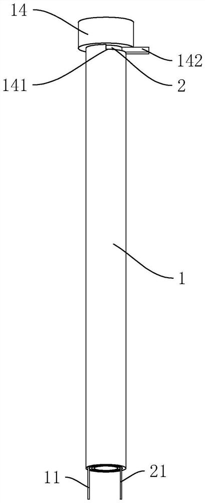
[0035] refer to figure 1 , a transforaminal lumbar fusion sleeve device, comprising an outer sleeve 1, and one end of the outer sleeve 1 is welded and fixed with a mounting box 14. The inner cavity of the outer casing 1 is rotatably connected with the middle casing 2, the outer wall of one end of the middle casing 2 close to the installation box 14 is welded and fixed with a rotating rod 142, and the outer wall of the installation box 14 is provided with a sliding groove 141. The rod 142 is slidably connected in the sliding groove 141. By pulling the rotating rod 142, the staff makes the rotating rod 142 slide in the sliding groove 141, so that the middle casing 2 rotates in the inner cavity of the outer casing 1, Through the rotation of the middle cannula 2, it can be used to protect the outlet root or the dural sac.

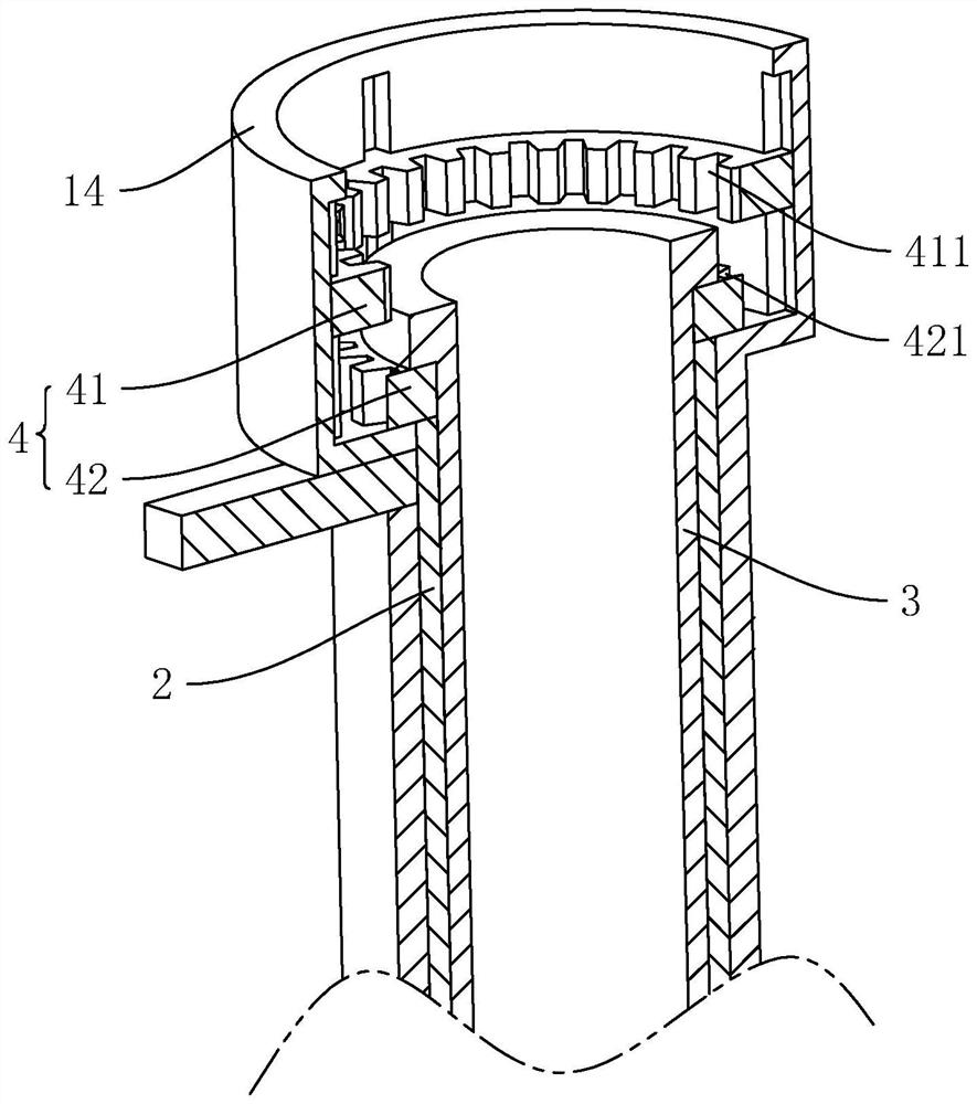
[0036] refer to figure 2 , the inner cavity of the installation box 14 is provided with a limiting member 4 for restricting the rotation of the middle-layer...

Embodiment 2

[0041] The difference between the second embodiment and the first embodiment is: refer to Figure 4 and Figure 5 , the outer wall of the middle-layer casing 2 is provided with an escape groove 24, the outer wall of the middle-layer casing 2 is provided with a limiting ball 22, and the outer wall of the outer-layer casing 1 is connected with a sliding cylinder 15, and the opening of the sliding cylinder 15 faces the limit At the position of the ball 22, the inner wall of the sliding cylinder 15 is slidably connected with the abutment block 12, and the end of the abutment block 12 facing the limit ball 22 is provided with a clamping hole 121, and the inner wall of the clamping hole 121 is glued and fixed. There is an anti-collision pad 1211 . In the present application, the anti-collision pad 1211 is made of rubber material. The arrangement of the anti-collision pad 1211 reduces the collision between the abutting block 12 and the outer wall of the limiting ball 22 . When the s...


PUM


Abstract

The invention relates to the technical field of fusion cages, in particular to an intervertebral foramen approach lumbar fusion cannula device which comprises an outer-layer cannula, an inner-layer cannula and an outer-layer cannula. The middle-layer sleeve is rotationally connected into the inner cavity of the outer-layer sleeve, and a second tongue-shaped sleeve is arranged on the middle-layer sleeve; the inner-layer sleeve is arranged in the inner cavity of the middle-layer sleeve in a sleeving manner; and the limiting piece is arranged on the outer wall of the outer-layer sleeve to limit the rotation of the middle-layer sleeve. The intervertebral fusion cage has the advantages that the export root and the dural sac are well protected, and the possibility of nerve injury caused by fusion cage imbedding and intervertebral space treatment is reduced.

Description

technical field [0001] The present application relates to the technical field of cages, and in particular, to a transforaminal lumbar fusion cannula device. Background technique [0002] With the acceleration of the aging process of my country's population, the incidence of degenerative diseases of the lumbar spine and other diseases has gradually increased. Due to the degeneration of the lumbar spondylolisthesis or instability and other intervertebral disc diseases, intervertebral fusion surgery is required. Transforaminal lumbar fusion is widely used in clinical practice and has the advantages of less trauma and faster recovery. Relevant operations through the safety triangle are the theoretical basis of transforaminal lumbar fusion. The safety triangle area consists of the outlet root, the edge of the dural sac, and the posterior superior border of the vertebral body. The risk of injury to the outlet root and dural sac requires attention when operating in this area. ...

Claims


Application Information

Patent Timeline
Patent Type & Authority Applications(China)
IPC IPC(8): A61B17/92A61B17/00A61B17/34A61F2/46
CPCA61B17/92A61B17/00234A61B17/00A61B17/3421A61B17/3468A61F2/4611A61B2017/00261A61B2017/0046A61F2002/4635
Inventor 黄鹏博吴志朋王红建宋晓磊
Owner 新里程安钢总医院
Why Eureka
Try Eureka