Automatic plate cutting device

A cutting device and plate technology, applied in auxiliary devices, welding/cutting auxiliary equipment, laser welding equipment, etc., can solve the problems of slow heating and reduced cutting efficiency at the cutting part of the plate, so as to improve cutting efficiency and heating efficiency. , Guarantee the effect of cutting efficiency

Pending Publication Date: 2022-07-08
CHONGQING COLLEGE OF ELECTRONICS ENG
View PDF1 Cites 0 Cited by
  • Summary
  • Abstract
  • Description
  • Claims
  • Application Information

AI Technical Summary

Problems solved by technology

[0004] The purpose of the present invention is to solve the problem in the prior art that the laser cutter heats the plate cutting part slowly during the moving process, resulting in a greatly reduced cutting efficiency, and proposes an automatic plate cutting device

Method used


Image

  • Automatic plate cutting device
  • Automatic plate cutting device
  • Automatic plate cutting device

Examples


Embodiment 1

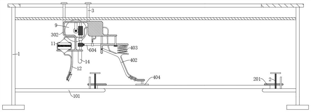
[0030] refer to Figure 1-7 , an automatic plate cutting device, including a fixed frame 1, a moving frame 302 horizontally sliding on the fixed frame 1, and also comprising: a laser cutter 14 fixed at the bottom of the moving frame 302, through the laser cutter 14, the plate is cut laser cutting.

[0031] The first fixed shaft 4 is fixedly connected to the bottom of the moving frame 302. The end of the first fixed shaft 4 away from the moving frame 302 is rotatably connected with a swinging plate 401. The bottom of the swinging plate 401 is connected with a spray head 1301. The nozzle of the spray head 1301 needs to be cut to align the plate. in front of.

[0032] The driving source arranged on the moving frame 302, when the driving source works, the swing plate 401 swings back and forth, and the moving frame 302 moves forward intermittently. The so-called intermittent movement is to move a certain distance, pause for a period of time, and then move forward again There is a...

Embodiment 2

[0069] refer to Figure 1-7 , which is basically the same as Example 1. On the basis of Example 1, the overall technical solution is further optimized to improve the stability during cutting.

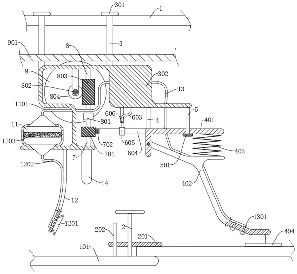
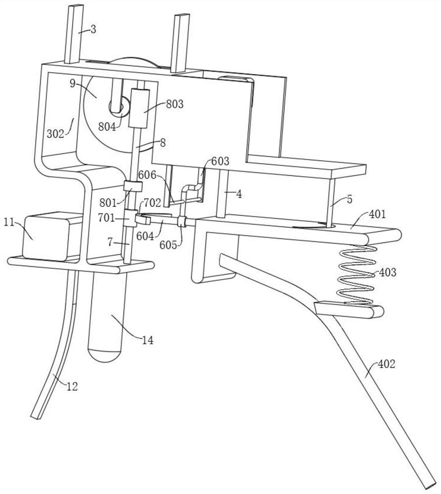
[0070] like figure 2 , 3 4. In order to improve the stability of the toggle rod 603 when moving, a second guide rod 606 fixed on the moving frame 302 is also included; the toggle rod 603 slides on the second guide rod 606 .

[0071] The toggle rod 603 is slid on the second guide rod 606, and the toggle rod 603 is deformed by force during the sliding process, which improves the stability of the work.

[0072] like figure 2 , 3 , 4, 5, in order to improve the stability of the swing plate 401 when it swings, it also includes a second fixed shaft 5 fixed at the bottom of the moving frame 302, the second fixed shaft 5 penetrates the swing plate 401, and the swing plate 401 is provided with a chute, The second fixed shaft 5 slides in the chute.

[0073] One end of the second fixing sh...


PUM


Abstract

The invention discloses an automatic plate cutting device, and belongs to the technical field of plate cutting, the automatic plate cutting device comprises a fixed frame and a movable frame horizontally sliding on the fixed frame, and further comprises a laser cutter fixed at the bottom of the movable frame; the first fixed shaft is fixedly connected to the bottom of the moving frame, the end, away from the moving frame, of the first fixed shaft is rotationally connected with a swing plate, and the bottom of the swing plate is connected with a spray head; the driving source is arranged on the moving frame; the movable frame intermittently moves forwards to automatically cut a plate, hot air generated at the cutting position is sucked away through the air suction assembly while cutting is conducted, then the hot air is sprayed out through the spray head, the spray head is driven by the swing plate to swing in a reciprocating mode, the hot air is sprayed to the periphery of the to-be-cut position of the front plate, preheating is conducted, and when the laser cutter moves to the upper portion, the cutting efficiency is improved. And the temperature of the cutting position of the plate can be rapidly increased, the heating efficiency is improved, and then the cutting efficiency is improved.

Description

technical field [0001] The invention relates to the technical field of panel cutting, in particular to an automatic panel cutting device. Background technique [0002] In recent years, with the rapid development of the economy and the increasing advancement of technology, the traditional industrial manufacturing industry has developed rapidly. With the rapid development of the industry, the use of sheet metal parts is increasing, and the quality requirements are also increasing It is getting higher and higher. Before many sheet metal parts are put into use, in order to meet the use requirements, they usually need to be cut to the specified size to make the plate parts meet the use requirements. At this time, a cutting device is needed to align the plate pieces are cut. [0003] However, currently on the market, when the existing plate cutting device is used to automatically cut the plate, especially for some plates with a long length, the laser cutter cuts the plate, and wh...

Claims


Application Information

Patent Timeline
Patent Type & Authority Applications(China)
IPC IPC(8): B23K26/38B23K26/08B23K26/70B23K37/04
CPCB23K26/38B23K26/0869B23K26/702B23K37/0443
Inventor 孙文成李卉
Owner CHONGQING COLLEGE OF ELECTRONICS ENG
Why Eureka
Try Eureka