Detachable cast-in-place concrete reserved hole mold

A concrete and hole-reserved technology, applied in the fields of formwork/formwork/work frame, on-site preparation of building components, connection of formwork/formwork/work frame, etc. The problem of high adhesion strength, etc., can improve the utilization rate and construction efficiency, facilitate control and quick disassembly, and facilitate recycling.

Pending Publication Date: 2022-07-08
北京中建润通机电工程有限公司
View PDF0 Cites 0 Cited by
  • Summary
  • Abstract
  • Description
  • Claims
  • Application Information

AI Technical Summary

Problems solved by technology

[0003] At present, high-rise buildings usually include a building body, multi-layer floors, and a large number of bridges, cables, and pipes. The bridges need to run through each floor, so corresponding reserved holes need to be opened in advance on the floor for the installation of bridges, cables, and pipes. When construction personnel lay mortar or concrete on the floor, in order to avoid the reserved hole, an isolation box is usually installed at the position of the reserved hole, and the isolation box is removed after the mortar or concrete is solidified; however, after the mortar or concrete solidifies It will adhere to the outer wall of the isolation box, and the isolation box is surrounded by mortar or concrete. The adhesion strength is relatively high, and it is difficult for the construction personnel to exert force on the isolation box, which makes it difficult to completely remove the isolation box. Therefore, destructive demolition is usually used, resulting in massive waste of resources

Method used


Image

  • Detachable cast-in-place concrete reserved hole mold
  • Detachable cast-in-place concrete reserved hole mold
  • Detachable cast-in-place concrete reserved hole mold

Examples


Embodiment 1

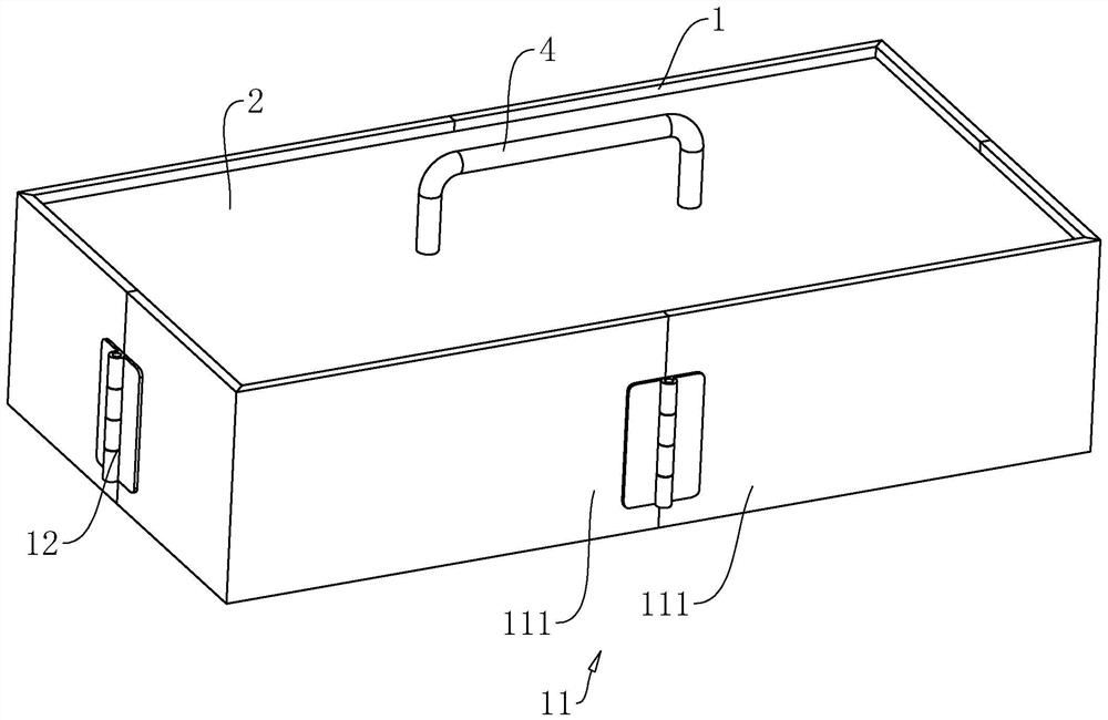
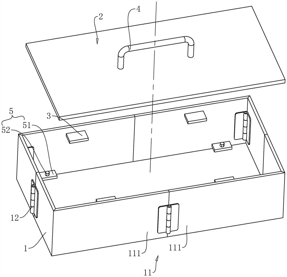
[0047] refer to figure 1 and figure 2 , the reserved hole mold includes an isolation box 1 that is hollow inside, and the isolation box 1 is a cuboid with top and bottom openings; the top opening of the isolation box 1 is provided with a top plate 2, and the side of the top plate 2 close to the isolation box 1 is opened along its circumferential direction There is a chamfer, and the chamfer is used for guiding and positioning when the top plate 2 is inserted into the opening at the upper end of the isolation box 1, so that the construction personnel can easily insert the top plate 2 into the isolation box 1. The inner side wall of the isolation box 1 is fixed with a plurality of mounting plates 3 along its circumferential direction. The multiple mounting plates 3 are located at the top opening of the isolation box 1 and are on the same horizontal plane. A handle 4 is also fixed above the top plate 2, and the handle 4 is used to facilitate the construction personnel to move t...

Embodiment 2

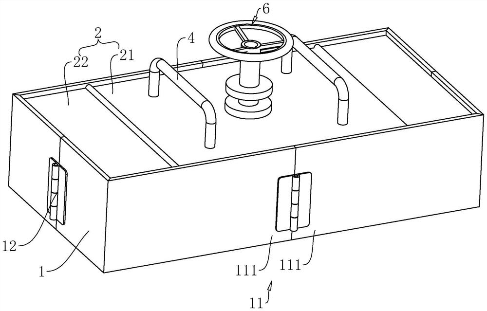
[0052] refer to figure 2 and image 3 , the difference from Embodiment 1 is that the top plate 2 includes a main support cover 21 and branch covers 22 hinged on both sides of the main support cover 21. The branch covers 22 are used to open the four end corners of the top of the isolation box 1, thereby facilitating the The construction personnel manipulate the connection assembly 5 to realize the installation and disassembly of the isolation box 1 and the floor slab. A synchronous shrinking mechanism 6 is also arranged between the isolation box 1 and the top plate 2. The synchronous shrinking mechanism 6 is used to drive the four side plates 11 to sag inward at the same time, so that the two support plates 111 in each side plate 11 are close to each other. Move to the inside of the side isolation box 1 .

[0053] refer to Figure 4 and Figure 5 , the synchronous retraction mechanism 6 includes a rotating shaft 61 rotatably connected to the top plate 2, the rotating shaft...


PUM


Abstract

The invention relates to a detachable cast-in-place concrete reserved hole mold, and relates to the field of building construction, and the reserved hole mold comprises an isolation box which is hollow and is provided with openings in the top and the bottom, a top plate detachably connected to the opening in the top of the isolation box, and a connecting assembly which is arranged on the inner side wall of the isolation box and is used for fixing the isolation box to a floor; the isolation box comprises four side plates, the adjacent side plates are hinged, and each side plate comprises two supporting plates which are hinged to each other; a plurality of mounting plates are fixedly arranged on the inner side wall of the isolation box in the circumferential direction of the isolation box, the mounting plates are located on the same horizontal plane, and the top plate abuts against the upper surfaces of the mounting plates at the same time; a synchronous contraction mechanism used for driving the four side plates to sink inwards at the same time is arranged between the isolation box and the top plate. The device has the effects that constructors can conveniently apply force to the isolation box to completely dismantle the isolation box, so that follow-up recycling of the isolation box is facilitated, and the resource utilization rate and the construction efficiency are improved.

Description

technical field [0001] The present application relates to the field of building construction, in particular to a detachable cast-in-place concrete reserved hole mold. Background technique [0002] The bridge frame is divided into trough type, tray type, ladder frame type, mesh type and other structures. The bridge frame in the building can be erected independently, or it can be laid on various buildings (structures) and pipe gallery supports. It is mainly used to protect cables, pipes, etc. [0003] At present, high-rise buildings usually include the building body, multi-storey floors and a large number of bridges, cables and pipes. The bridges need to run through each floor, so the corresponding reserved holes need to be opened in advance on the floors for the installation of bridges, cables and pipes. When the construction workers lay mortar or concrete on the floor, in order to avoid the reserved holes, they usually install an isolation box at the position of the reserve...

Claims


Application Information

Patent Timeline
IPC IPC(8): E04G15/06E04G17/00
CPCE04G15/063E04G17/00
Inventor 赵金鹏张庆博李金刚魏思远王磊
Owner 北京中建润通机电工程有限公司
Why Eureka
Try Eureka