
Moving coil with composite guide structure for electric vibration table

An electric vibrating table and composite guiding technology, which is used in the testing of machine/structural components, vibration testing, measuring devices, etc., can solve the problems of uneven distribution of lubricating oil film, affecting waveforms, and interference of moving coils, reducing surface hardness, The effect of reducing bearing mass and reducing interference

Pending Publication Date: 2022-07-08
6 DOF VIBRATION TESTING DEVICE WITH ELECTRODYNAMIC EXCITATION +1
View PDF0 Cites 0 Cited by
  • Summary
  • Abstract
  • Description
  • Claims
  • Application Information

AI Technical Summary

Problems solved by technology

[0005] In view of the above situation, in order to overcome the defects of the prior art, the present invention provides a moving coil with a composite guiding structure for the electric vibrating table, which effectively solves the problem that the guiding structure of the existing moving coil generally uses a linear bearing, and the guiding structure of the bearing The shafts are generally made of steel shafts. The advantages of linear bearings are large stroke, small size, and easy installation; but the disadvantage is that when working for a long time, especially at high frequency, due to the small displacement, there will be slippage between the ball and the guide shaft. , the distribution of the lubricating oil film on the ball becomes uneven, and dry friction will occur. The friction and collision between the ball and the guide shaft will generate interference signals to the moving coil and affect the waveform.

Method used


Image

  • Moving coil with composite guide structure for electric vibration table
  • Moving coil with composite guide structure for electric vibration table
  • Moving coil with composite guide structure for electric vibration table

Examples


Embodiment 1

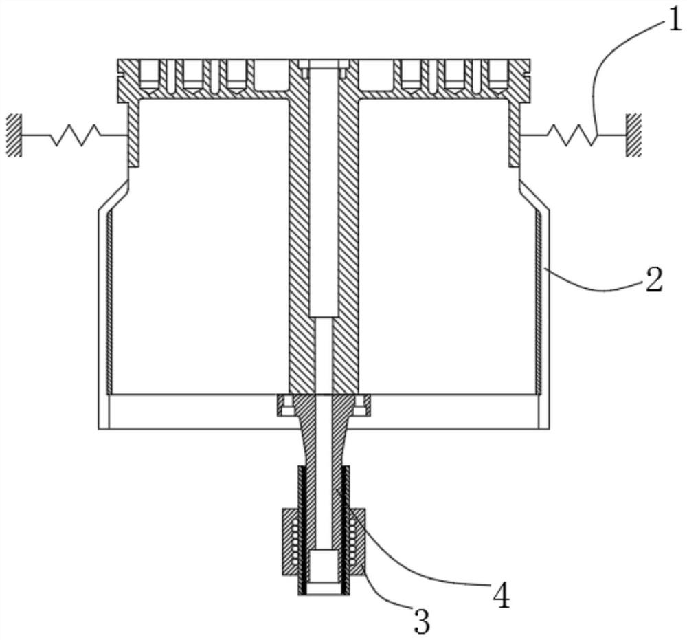
[0021] Example one, by Figure 1-3 Given, the present invention provides a moving ring with a composite guide structure for an electrodynamic vibration table, comprising a leaf spring 1, a moving ring 2, a bearing 3 and a composite guide shaft mechanism 4, the upper circumferential outer ring of the moving ring 2 is Four leaf springs 1 are evenly distributed, a composite guide shaft mechanism 4 is installed on the bottom of the moving ring 2, and a bearing 3 is installed on the outer side of the composite guide shaft mechanism 4;

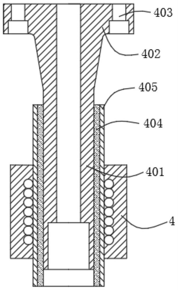
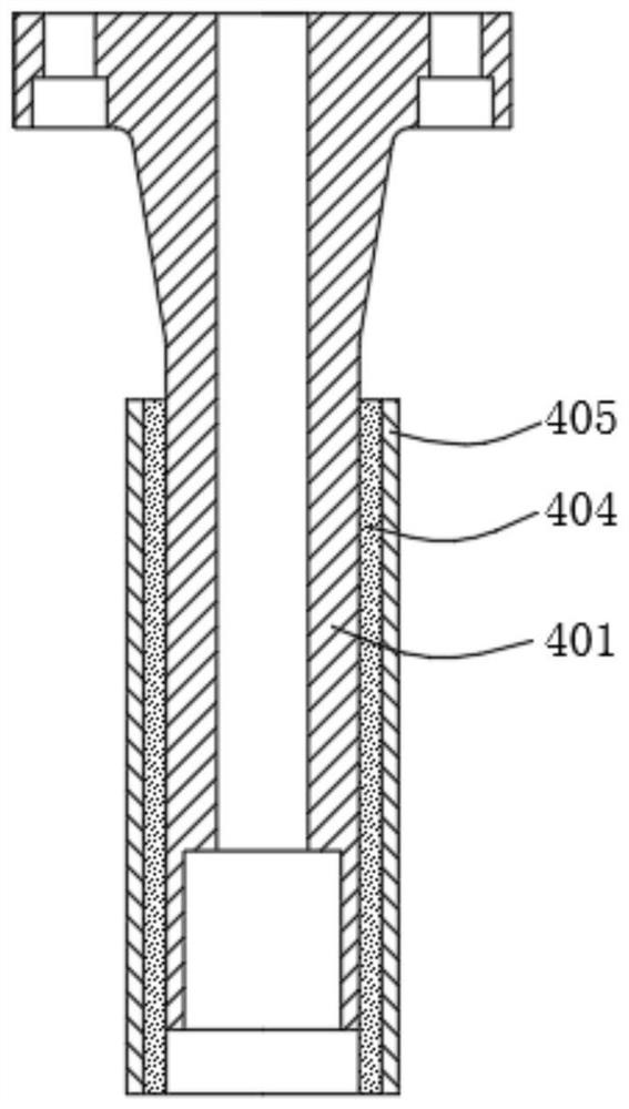
[0022] The composite guide shaft mechanism 4 includes a shaft core 401, a mounting plate 402, a mounting hole 403, a rubber interlayer 404 and a sleeve 405. The top end of the shaft core 401 is provided with a mounting plate 402, and the edge of the mounting plate 402 is provided with several mounting holes 403 , the outer side of the shaft core 401 is provided with a rubber interlayer 404, and the outer side of the rubber interlayer 404 is sleeved ...

Embodiment 2

[0024] In the first embodiment, the connection between the mounting plate 402 and the moving coil 2 is inconvenient. figure 1 , as another preferred embodiment, the difference from the first embodiment is that the mounting plate 402 is connected with the moving coil 2 through bolts, which is convenient for the connection and use of the mounting plate 402 and the moving coil 2 .

Embodiment 3

[0026] In the first embodiment, the rubber interlayer 404 is inconvenient to use, refer to Figure 1-3 , as another preferred embodiment, the difference from the first embodiment is that the thickness of the rubber interlayer 404 is 3 mm, which is convenient for the use of the rubber interlayer 404 .


PUM


Abstract

A moving coil with a composite guide structure for an electric vibration table solves the problems that a guide structure of an existing moving coil generally uses a linear bearing, a guide shaft of the bearing generally adopts a steel shaft, during long-time work, especially high-frequency work, due to the fact that displacement is small, a sliding phenomenon exists between balls and the guide shaft, distribution of lubricating oil films on the balls is uneven, and the service life of the balls is prolonged. The invention relates to a composite guide shaft mechanism, in particular to a composite guide shaft mechanism, which solves the problems that four plate springs are uniformly distributed on the outer ring of the circumference of the upper part of a moving coil, a bearing is arranged on the outer ring of the circumference of the upper part of the moving coil, and the composite guide shaft mechanism is arranged at the bottom of the moving coil. A bearing is mounted on the outer side of the composite guide shaft mechanism; the bearing is novel in structure and ingenious in conception, damping is increased, interference of the bearing can be absorbed and weakened, the vibration waveform can be improved at high frequency, the overall strength is high, the bearing mass is reduced, and machining is convenient.

Description

technical field [0001] The invention relates to the field of environmental test and reliability test equipment, in particular to a moving coil with a composite guide structure for an electrodynamic vibration table. Background technique [0002] Vibration-induced product failures account for a large proportion of all product problems. Vibration testing is also an important part of environmental testing and reliability testing. Under laboratory conditions, the vibration test of the specimen can be used to find product problems in time in the design stage, saving a lot of time and economic costs. Whether the vibration equipment can meet the test requirements and whether it can generate accurate vibration excitation plays a key role in the quality of the test. [0003] The electric vibrating table is the main vibration excitation equipment. For small and medium-sized vibrating tables, the guiding structure of the moving ring generally uses linear bearings, and the guiding shaf...

Claims


Application Information

Patent Timeline
Patent Type & Authority Applications(China)
IPC IPC(8): G01M7/02
CPCG01M7/02G01M7/022
Inventor 李杨张奎华夏树杰曹小波刘军底红岩宋科杰田振强
Owner 6 DOF VIBRATION TESTING DEVICE WITH ELECTRODYNAMIC EXCITATION
Learn More