Detachable cable assembly
A cable assembly, detachable technology, applied in the field of detachable cable assemblies, can solve the problems of scrapped connectors, performance problems, inability to disassemble and reuse, etc., and achieve the effect of easy reset and avoiding loss of parts
- Summary
- Abstract
- Description
- Claims
- Application Information
AI Technical Summary
Problems solved by technology
Method used
Image

Examples
Embodiment 1
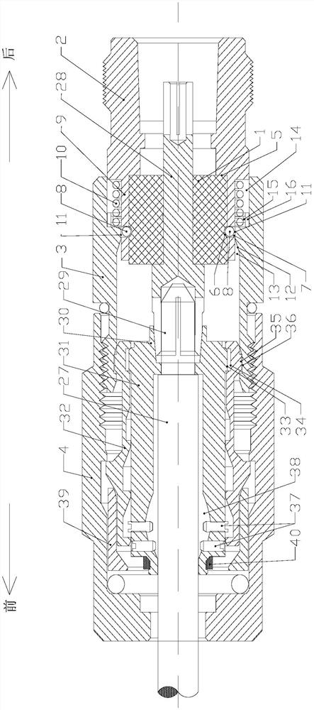
[0033] like figure 1 As shown, a detachable cable assembly includes a casing, an insulator 1 and a cable installed in the casing, and the casing includes a rear casing 2, a positioning casing 3 and a locking casing that are detachably connected in sequence from back to front 4. The tail housing 2 is slidably connected with the positioning housing 3 , and the locking housing 4 is connected with the positioning housing 3 through internal threads and external threads that cooperate with each other.
[0034] The cable includes a cable body 27 and pins 28 that are connected to each other, and the insulator 1 presses the pins 28 into the tail housing 2, that is, the insulator 1 is tightly fitted with the pins 28 and the tail housing 2, and the insulator 1 is in a tight fit. It is fixed with the pin 28 by the barb snap connection, and the two can move together.
[0035] The front end of the pin 28 is provided with a petal-shaped clamping claw 29, and the tail of the cable body 27 i...
Embodiment 2
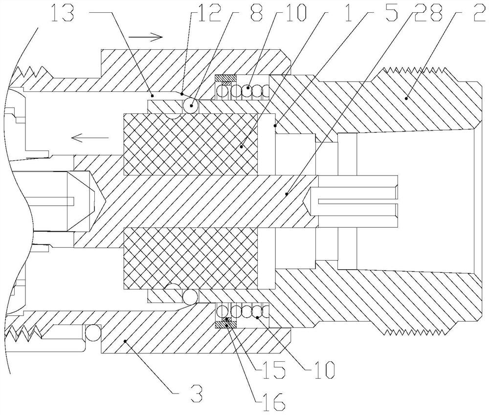
[0050] like figure 2 As shown, this embodiment adds a limiting structure to the positioning housing 3 on the basis of the first embodiment, so that the positioning housing 3 can be assembled accurately. This embodiment also includes an elastic clamp 15 and a limit ring 16 , which are located in the space enclosed by the annular groove 14 and the cylindrical body 9 . In the free state, the elastic member 10, that is, the front end of the compression spring, is pressed by an elastic clamp 15 to increase the friction force between the compression spring and the cylinder 9; the elastic clamp 15 is fixedly connected to the limit ring 16 outside, elastic The clamp 15 also exerts an outward pressure on the limit ring 16 , so that the limit ring 16 presses against the annular groove 14 outward. The compression spring and the elastic clamp 15 keep the limit ring 16 in a relatively fixed state, and the limit ring 16 is in close contact with the front side wall of the annular groove 14...
Embodiment 3
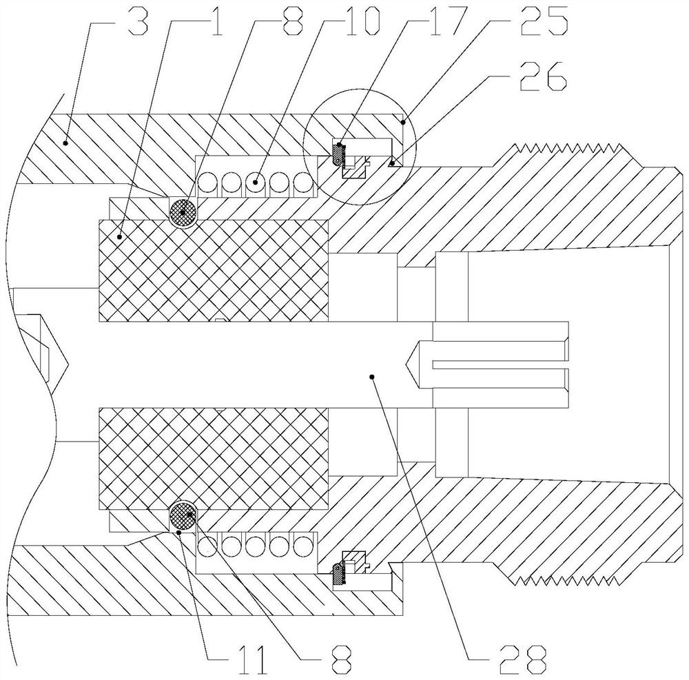
[0055] like Figure 3 to Figure 6 As shown, this embodiment adds another limiting structure to the positioning housing 3 on the basis of the first embodiment. A limit assembly 17 for limiting the positioning shell 3 is provided on the outer wall of the tail housing 2 near the rear end of the positioning shell 3 . The limit assembly 17 includes a lock ring 18 and a rotation pin 19 . The tail housing 2 is formed with a ring groove and a pin groove that communicates with the ring groove. The rotating pin 19 is located in the pin groove and is hinged to the tail housing. The lock ring 18 is embedded in the ring groove and is locked in the ball 8 When the insulator 1 is tightened, the rotating pin 19 is pressed against the front end surface of the locking ring 18 to be in a vertical state, thereby preventing the rear end surface of the positioning housing 3 from moving backwards. The top wall of the lock ring 18 is provided with a groove body 1 20, which is used to accommodate the...
PUM
 Abstract
Description
Claims
Application Information
 - R&D
- Intellectual Property
- Life Sciences
- Materials
- Tech Scout
- Unparalleled Data Quality
- Higher Quality Content
- 60% Fewer Hallucinations
Browse by: Latest US Patents, China's latest patents, Technical Efficacy Thesaurus, Application Domain, Technology Topic, Popular Technical Reports.
© 2025 PatSnap. All rights reserved.Legal|Privacy policy|Modern Slavery Act Transparency Statement|Sitemap|About US| Contact US: help@patsnap.com