Converter direct current side capacitance minimization method based on high-frequency transformer

A DC-side capacitor and high-frequency transformer technology, applied in the direction of converting AC power input to DC power output, converting DC power input to DC power output, instruments, etc., can solve the problem of large equipment volume and weight, short life, and increased equipment cost and other issues, to achieve high equipment power density, improve power density, and achieve simple and reliable results

Pending Publication Date: 2022-07-08
XI AN JIAOTONG UNIV
0 Cites 0 Cited by

AI-Extracted Technical Summary

Problems solved by technology

[0004] However, the converter still faces a technical challenge, that is, the capacitance value of the DC side capacitor needs to be further optimized to increase the power density
Traditional isolated converter units transfer power fluctuations to the DC side when processing ...

Method used

In the past, the isolated medium-voltage high-power converter unit transferred the power fluctuation to the DC side when processing the low-frequency fluctuation power input by the AC port, and was buffered by the DC side capacitor, and the capacitor array of large capacitance value increased the size of the device. The volume and weight are not conducive to the improvement of the power density of the devic...

Abstract

The invention discloses a converter direct current side capacitance minimization method based on a high-frequency transformer, and the method comprises the steps: taking an input converter as a reference direction, adding the instantaneous power of all ports, obtaining the total fluctuation power Pf, distributing the power to each direct current side capacitor, and calculating the power PCi which needs to be buffered by each direct current side capacitor; the input power Poi of each port is detected, the power transmitted to the high-frequency transformer by each high-frequency converter is controlled, so that the average value Pi of the power in a high-frequency period is equal to the difference value between the input power Poi of the port and the buffer power PCi of the direct-current side capacitor, and the value is reduced without adding extra components; according to the rule that fluctuation power of an alternating current port is counteracted through a magnetic circuit, the fluctuation power buffered at the capacitor is reduced, the capacitance value of the direct current side capacitor is reduced to the maximum extent, and therefore the size and weight of the capacitor are reduced, and the technical requirement for power density is met.

Application Domain

Ac-dc conversionDc-dc conversion +1

Technology Topic

Computational physicsCapacitance +7

Image

  • Converter direct current side capacitance minimization method based on high-frequency transformer
  • Converter direct current side capacitance minimization method based on high-frequency transformer
  • Converter direct current side capacitance minimization method based on high-frequency transformer

Examples

  • Experimental program(1)

Example Embodiment

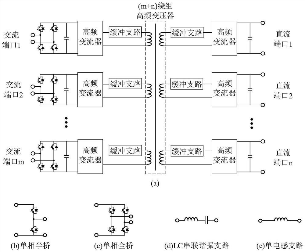
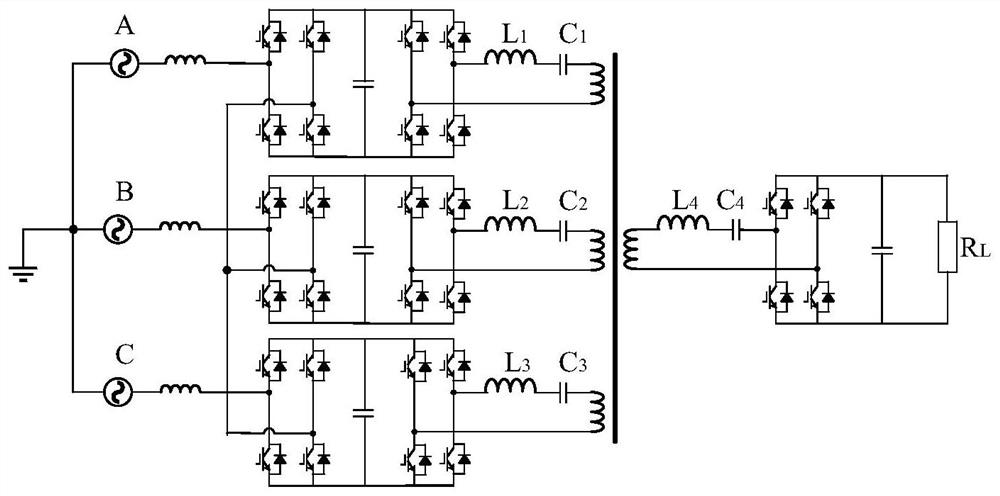
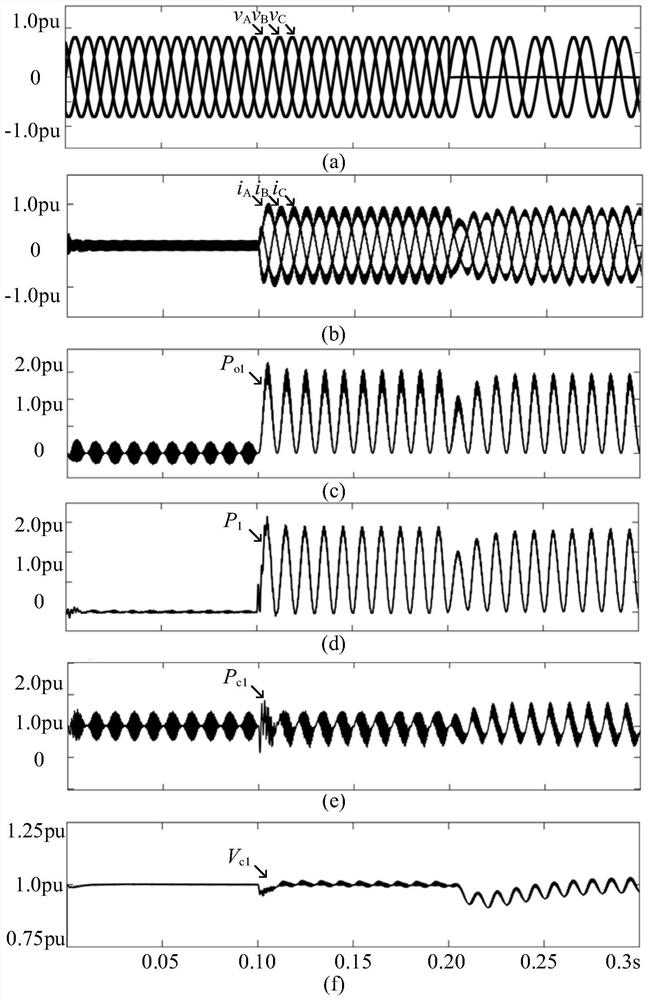
[0025] In order to make those skilled in the art better understand the technical solutions of the present invention, the technical solutions in the embodiments of the present invention will be clearly and completely described below with reference to the accompanying drawings in the embodiments of the present invention. Obviously, the described The embodiments are only some of the embodiments of the present invention, but not all of the embodiments. Based on the embodiments of the present invention, all other embodiments obtained by persons of ordinary skill in the art without creative work shall fall within the protection scope of the present invention.
[0026] It should be noted that when an element is referred to as being "disposed on" another element, it can be directly on the other element or intervening elements may also be present. When an element is referred to as being "connected" to another element, it can be directly connected to the other element or intervening elements may also be present. The terms "vertical", "horizontal", "left", "right" and similar expressions used herein are for the purpose of illustration only and do not represent the only embodiment.
[0027] Unless otherwise defined, all technical and scientific terms used herein have the same meaning as commonly understood by one of ordinary skill in the art to which this invention belongs. The terms used herein in the description of the present invention are for the purpose of describing specific embodiments only, and are not intended to limit the present invention. As used herein, the term "and/or" includes any and all combinations of one or more of the associated listed items.
[0028] The previous isolated medium-voltage high-power converter unit transfers the power fluctuation to the DC side when dealing with the low-frequency fluctuation power input from the AC port, which is buffered by the DC-side capacitor. The weight is not conducive to the improvement of the power density of the device. Aiming at the serious power density problem brought by the large-capacitance capacitor array, the present invention uses the magnetic circuit coupling method to offset the fluctuating power to reduce the capacitance value. During specific implementation, the topology form, buffer branch branch form, switching frequency and switching tube type of the high-frequency converter of the AC port are not limited.
[0029] The invention proposes a method for reducing the capacitance value of the DC side capacitance of the converter based on a high-frequency transformer, without adding additional components, and reducing the fluctuation of the buffer at the capacitor according to the law that the fluctuating power of the AC port is offset by the magnetic circuit Power, minimize the capacitance of the DC side capacitor, thereby reducing the volume and weight of the capacitor, and solving the technical requirements of power density.
[0030] To explain how this method works, we figure 1 The illustrated converter based on a high frequency transformer with (m+n) windings is described as an example. The converter consists of a (m+n) winding high-frequency transformer, (m+n) buffer branches, (m+n) high-frequency converters, (m+n) DC side support capacitors and It consists of m interface converters. A buffer branch is connected in series to the terminals of each winding of the (m+n) winding high-frequency transformer, the other end of each buffer branch is connected to the AC port of the high-frequency converter, and each high-frequency converter is connected to a DC side capacitor, each DC side capacitor is cascaded with an interface converter to lead out the AC port or directly lead out to form a DC port.
[0031] The frequency of the high-frequency transformer of the present invention is any frequency in the range of several hundreds of hertz to several hundreds of kilohertz.
[0032] where m and n are positive integers.
[0033] The main function of the high frequency converter is to provide square wave voltage for the high frequency transformer. figure 1 (b) and figure 1 The single-phase half-bridge or single-phase full-bridge circuit shown in (c). The buffer branch adopts such as figure 1 (d) and figure 1The LC series resonant branch or the single inductive branch shown in (e). The interface converter adopts a single-phase full-bridge converter structure. The converter has at least one AC port, that is, the number of AC ports is one, two to m. The number of DC ports can be zero, one to n. The type of switch tube is not limited, and IGBT, MOSFET or other switch tube can be used.
[0034] Each port takes the input converter as the reference direction, and sums the instantaneous power input from all ports to obtain the total fluctuating power (P f ).
[0035] Among them, the sum of the DC components of the input power of each port is zero, and the fluctuating power components of each AC port cancel each other to a certain extent, so the total fluctuating power P f to the smaller value. The high-frequency converters connected to each winding of the high-frequency transformer are equipped with capacitors on the DC side to convert the total fluctuating power P. f It is equally distributed or distributed to each winding in any other proportion, so as to calculate the expected power buffered by the DC side capacitance of each winding (P ci ),in i is the ith DC side capacitor. Detect the input power of each port (P oi ), control the power output from the high-frequency converter of each winding to the transformer, so that the average value of the power in the high-frequency period (P i ) is equal to the winding input power (P oi ) and the buffered power (P ci ) difference power, that is, P i =P oi -P ci , it can be known from the law of conservation of power that it satisfies Accordingly, the low-frequency fluctuating power input from the AC port can be transferred to the high-frequency transformer to cancel each other out, which greatly reduces the amount of fluctuating power buffered by the DC-side capacitor, thereby reducing the capacitance value of the capacitor and improving the system power density.
[0036] When distributing the buffered power required by the DC side capacitors of each winding, different power distribution methods are required for different combinations of high-frequency converters and buffer branches:
[0037] (1) When the high-frequency converter adopts a single-phase full-bridge or single-phase half-bridge converter, the buffer branch is an LC resonant branch, and the switching frequency of the high-frequency converter is close to but not equal to the LC resonant frequency, When allocating the total fluctuating power to the DC side capacitors of each winding, it can be equally distributed or distributed in any other proportion, and the power output from the high-frequency converter to the high-frequency transformer can be precisely controlled through the phase-shift control strategy;
[0038] (2) When the high-frequency converter adopts a single-phase full-bridge or single-phase half-bridge converter, the buffer branch is an LC resonant branch, and the switching frequency of the high-frequency converter is equal to the LC resonant frequency, the total fluctuation When the power is distributed to the DC side capacitors of each winding, it can only be distributed evenly. Each high-frequency converter adopts a square wave switching signal with the same phase and a duty cycle of 50%, and the power buffered by the DC side capacitors of each port is equal;
[0039] (3) When the high-frequency converter adopts a single-phase full-bridge converter and the buffer branch is an LC resonant branch, the total fluctuating power can be distributed in any other proportion when it is distributed to the DC side capacitors of each winding. The control strategy precisely controls the power output from the high frequency converter to the high frequency transformer.
[0040] The following describes in detail with reference to specific examples.
[0041] by figure 2 The three-phase AC-DC converter shown is taken as an example to illustrate the proposed method. The circuit is a three-phase AC-DC converter with 3 windings on the primary side and 1 winding on the secondary side with a total of four windings. Both the interface converter and the high-frequency converter use a full-bridge circuit, and the buffer branch uses an LC resonant branch. The switching frequency of the high frequency converter is equal to the LC resonant frequency. It should be understood that the specific embodiments described herein are only used to explain the present invention, but not to limit the present invention.
[0042] The parameter information such as the voltage and power level of the circuit is collected in Table 1. The simulation model of the Matlab/Simulink three-phase AC-DC converter constructed on this basis fully achieves the expected design goal and realizes the function of reducing the capacitance value. Simulation waveforms are collected in image 3 middle.
[0043] Table 1 The main parameters of the simulation model
[0044]
[0045] image 3 Shown are the simulated waveforms of the three-phase AC port on the input side of the high-frequency transformer. Among them, the sub-picture (a) is the three-phase AC voltage waveform; the sub-picture (b) is the three-phase AC current waveform; the sub-picture (c) is the A-phase port input power P after the A-phase AC voltage and the A-phase AC current are multiplied. o1; Sub-figure (d) is the average power P after multiplying the square wave voltage output by the A-phase high-frequency converter and the winding resonant current and removing the switching sub-harmonic 1; Sub-figure (e) is the input power P of the A-phase port o1 and high frequency converter output power P 1 The power P that needs to be borne by the DC side capacitor after subtraction c1; Sub-figure (f) is the DC side capacitor voltage V of the A-phase port c1.
[0046] In the initial stage of the simulation, the system runs with no load; at t=0.1 seconds, the load absorbed power is stepped from 0w to 200kw rated power; at t=0.2 seconds, the input side C-phase single-phase ground fault, and the load is derated at the same time. . In the whole simulation process, the fluctuation component of the input power of the three-phase port is cancelled by the magnetic circuit of the transformer. After the A-phase input power is subtracted from the output power of the high-frequency converter, the fluctuation power that needs to be borne by the DC side capacitor is very small. In the case of the capacitance value of the DC side capacitor, the voltage fluctuation amplitude is still controlled within 5%. When the capacitance value of the capacitor is 200μF, even under the worst working conditions, the capacitor voltage ripple is within 100V, accounting for about 5% of the voltage setting value (2000V). Compared with the traditional series H-bridge structure, the The converter reduces the capacitance value by more than 66%, which proves its good capacitance reduction ability.
[0047] It can be seen that, under the same ripple index requirement, the method of offsetting the fluctuating power of the AC port through the coupled magnetic circuit proposed by the present invention greatly reduces the power buffered by the DC side capacitor, thereby realizing the minimization of the capacitance value. , which verifies the effectiveness of the proposed method.
[0048] From reading the above description, many embodiments and many applications beyond the examples provided will be apparent to those skilled in the art. The scope of the present teachings should, therefore, be determined not with reference to the above description, but should instead be determined with reference to the preceding claims, along with the full scope of equivalents to which such claims are entitled. The disclosures of all articles and references, including patent applications and publications, are incorporated herein by reference for the purpose of being comprehensive. The omission of any aspect of the subject matter disclosed herein in the preceding claims is not intended to disclaim such subject matter, nor should it be construed that the applicant has not considered such subject matter to be part of the disclosed subject matter.
[0049] The above content is a further detailed description of the present invention, and it cannot be considered that the specific embodiments of the present invention are limited to this. Several simple deductions or substitutions should be regarded as belonging to the protection scope of the present invention determined by the submitted claims.

PUM

no PUM

Description & Claims & Application Information

We can also present the details of the Description, Claims and Application information to help users get a comprehensive understanding of the technical details of the patent, such as background art, summary of invention, brief description of drawings, description of embodiments, and other original content. On the other hand, users can also determine the specific scope of protection of the technology through the list of claims; as well as understand the changes in the life cycle of the technology with the presentation of the patent timeline. Login to view more.

Similar technology patents

Marking method and marking device

InactiveCN107262934AImprove power densityIncrease destructive power
Owner:HANS LASER TECH IND GRP CO LTD +1

Five-level H-bridge converter and pre-charging method thereof

Owner:WUHAN MARINE ELECTRIC PROPULSION RES INST CHINA SHIPBUILDING IND CORP NO 712 INST

Stable lithium ion battery with high capacitance

InactiveCN103606666AImprove high-magnification performanceImprove power density
Owner:JIANGSU TENPOWER LITHIUM

Classification and recommendation of technical efficacy words

Why Eureka
Try Eureka