Dynamic balance intelligent detection device for automobile transmission shaft

A technology of intelligent detection and transmission shaft, which is applied in the direction of static/dynamic balance testing, measuring devices, auxiliary devices, etc., can solve the problems of less support, long processing time, and not being combined with other processing procedures, so as to improve processing efficiency, The effect of reducing transportation time and flexible docking

Pending Publication Date: 2022-07-12
邵彭伟
View PDF0 Cites 3 Cited by
  • Summary
  • Abstract
  • Description
  • Claims
  • Application Information

AI Technical Summary

Problems solved by technology

[0002] The transmission shaft is an important part of power transmission in the automobile transmission system. Its function is to transmit the power of the engine to the wheels together with the gearbox and drive axle, so that the car can generate driving force, and the transmission shaft is a high-speed, less-supported rotation body, so its dynamic balance is crucial. Generally, the transmission shaft must undergo a dynamic balance test before leaving the factory and adjust it on a balancing machine. The traditional process of adjusting the transmission shaft is mostly set separately, which is not compatible with other processing procedures. At the same time, for the detection of each transmission shaft, it takes a long time to detect due to the need for more accurate measurement by the detection machine. The processing time of qualified parts will be very long, so it is necessary to provide an intelligent detection device for dynamic balance of automobile drive shaft to solve the above problems

Method used


Image

  • Dynamic balance intelligent detection device for automobile transmission shaft
  • Dynamic balance intelligent detection device for automobile transmission shaft
  • Dynamic balance intelligent detection device for automobile transmission shaft

Examples


Embodiment Construction

[0036] In order to further understand the features, technical means, and specific goals and functions of the present invention, the present invention will be described in further detail below with reference to the accompanying drawings and specific embodiments.

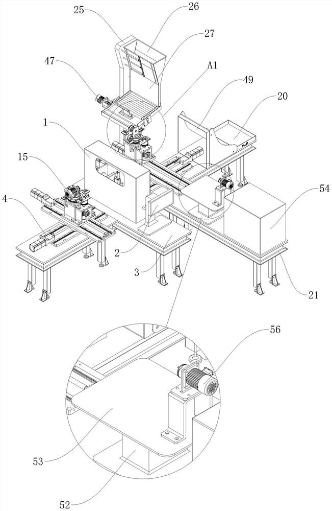
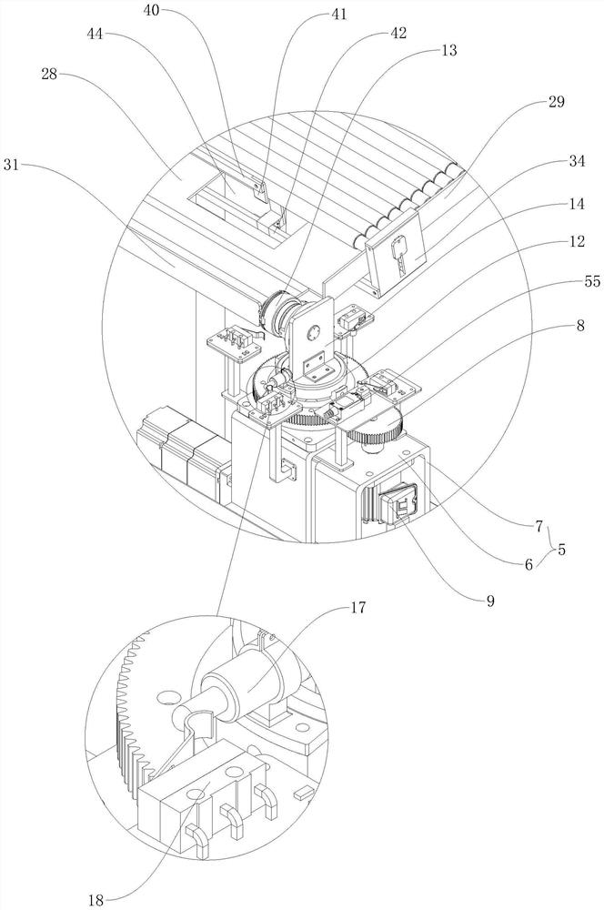
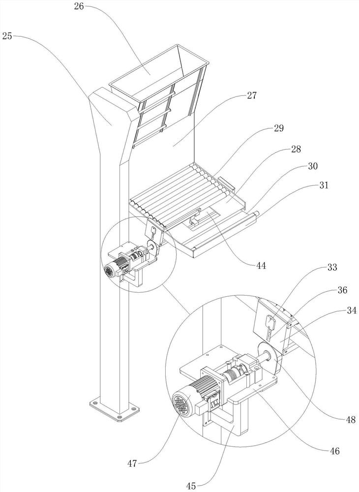
[0037] refer to Figure 1 to Figure 13 The shown one is an intelligent detection device for the dynamic balance of automobile transmission shaft, including a dynamic balance detection machine composed of a detector 1 and a display 2, and also includes a discharging component, a material moving component, a blanking component and a docking component. The component and the docking component are located on both sides of the moving component, and the blanking component is located on the side of the moving component for collecting and testing qualified transmission shafts. The moving component includes two XY axis horizontal moving mechanisms arranged at intervals along the horizontal direction and The No. 1 gripping jaw m...


PUM


Abstract

The invention relates to the field of quality detection of automobile transmission shafts, in particular to an intelligent detection device for dynamic balance of an automobile transmission shaft, which comprises a dynamic balance detection machine consisting of a detector and a display, and further comprises a discharging assembly, a material moving assembly, a blanking assembly and a butt joint assembly, the material moving assembly comprises two XY-axis horizontal moving mechanisms and two first clamping jaw mechanisms, each first clamping jaw mechanism is provided with a clamping jaw end, a rotating mechanism is arranged below each first clamping jaw mechanism, the discharging assembly comprises a valve mechanism, and the butt joint assembly comprises a second clamping jaw mechanism. All procedures of finished product blanking collection and defective product welding processing are integrated together, the transportation time between each procedure is shortened, the processing efficiency of the transmission shaft from a to-be-detected piece to a qualified piece is greatly improved, meanwhile, the material moving assembly of the device adopts four-direction rotating movement to be in butt joint with different procedures, and the working efficiency is greatly improved. And the butt joint between the working procedures is more flexible.

Description

technical field [0001] The invention relates to the field of quality detection of automobile transmission shafts, in particular to an intelligent detection device for dynamic balance of automobile transmission shafts. Background technique [0002] The drive shaft is an important part of the transmission of power in the car drive train. Its function is to transmit the power of the engine to the wheels together with the gearbox and the drive axle, so that the car can generate driving force. Therefore, its dynamic balance is very important. Generally, the drive shaft must be tested for dynamic balance before leaving the factory, and adjusted on the balancing machine. The traditional process of adjusting the drive shaft is mostly set separately, which is not integrated with other processing processes. At the same time, for the detection of each transmission shaft, since the detection machine needs to measure more accurately, it takes a long time to detect. If the time for other ...

Claims


Application Information

Patent Timeline
Patent Type & Authority Applications(China)
IPC IPC(8): B07C5/02B07C5/34B07C5/36B07C5/38B23K37/04B65G47/90G01M1/16
CPCB07C5/02B07C5/34B07C5/362B23K37/0426B07C5/38B65G47/902B65G47/905G01M1/16
Inventor 邵彭伟
Owner 邵彭伟
Why Eureka
Try Eureka