
Engine supercharging mechanism and application thereof

An engine and drive shaft technology, which is applied to combustion engines, machines/engines, internal combustion piston engines, etc., can solve the problems of reduced intake air volume, engine power reduction, and exhaust obstruction, etc., to achieve increased intake air volume and exhaust gas Smooth, full-burning effect

Pending Publication Date: 2022-07-12
聂其东
View PDF0 Cites 0 Cited by
  • Summary
  • Abstract
  • Description
  • Claims
  • Application Information

AI Technical Summary

Problems solved by technology

[0004] However, when the exhaust gas from the engine pushes the turbine to move, it is subjected to the reaction force of the turbine, which makes the exhaust blocked, and will be affected by the expansion of the air pressure in the cylinder during the next intake, resulting in a decrease in intake air volume and a reduction in engine power. Therefore, the present invention proposes an engine supercharging mechanism capable of solving the above problems and its application

Method used


Image

  • Engine supercharging mechanism and application thereof
  • Engine supercharging mechanism and application thereof

Examples


Embodiment 1

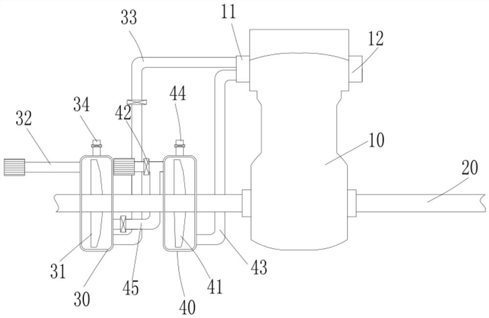
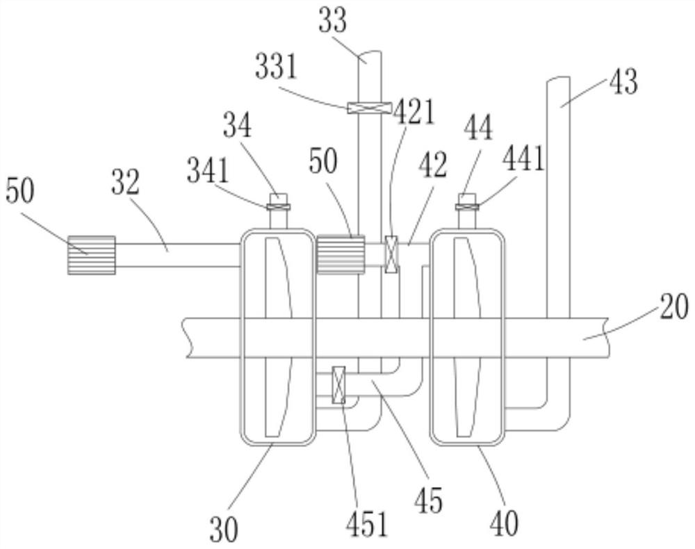
[0024] The present invention provides a technical solution: an engine supercharging mechanism includes an engine body 10, the engine body 10 is connected with a drive shaft 20, a first casing 30 is mounted on the drive shaft 20, and a first impeller is arranged in the first casing 30 31. The first impeller 31 is connected with the drive shaft 20; one end of the first casing 30 is provided with an air intake pipe, and the other end is provided with an air guide pipe, and the air guide pipe is connected with the intake valve 11 of the engine body 10; one end of the first casing 30 is provided with a The first air intake pipe 32 has a first air intake pipe 33 at the other end. The first air intake pipe 33 is connected to the intake valve 11 of the engine body 10 . A first exhaust pipe 34 is disposed on the upper side of the first housing 30 . A first solenoid valve 341 is installed on the gas pipe 34 .

[0025] Specifically, when the engine body 10 is working, the internal piston...

Embodiment 2

[0027] On the basis of Embodiment 1, a second casing 40 is installed on the drive shaft 20 , a second impeller 41 is disposed in the second casing 40 , the second impeller 41 is connected to the drive shaft 20 , and one end of the second casing 40 is disposed There is a second intake pipe 42 , and the other end is provided with a second air conduit 43 , and the second air conduit 43 is connected to the intake valve 11 of the engine body 10 .

[0028] Specifically, the engine body 10 can simultaneously drive the first impeller 31 and the second impeller 41 to rotate, and transport air into the engine body 10 through the first air duct 33 and the second air duct 43 to effectively increase the intake air volume.

Embodiment 3

[0030]On the basis of Embodiment 1, a second housing 40 is mounted on the drive shaft 20 , one end of the second housing 40 is provided with a second air intake pipe 42 , and the other end is provided with a second air conduit 43 , and the second air conduit 43 is connected to The engine body 10 is connected to the intake valve 11, the second casing 40 is provided with a second impeller 41, and the second impeller 41 is connected to the drive shaft 20; the upper side of the second casing 40 is provided with a second exhaust pipe 44, the second A second solenoid valve 441 is installed on the exhaust pipe 44; a third solenoid valve 331 is installed on the first air duct 33, and a third air intake pipe 45 is connected to the second air intake pipe 42. The third air intake pipe 45 is connected to the first shell The engine body 30 is connected, the second intake pipe 42 is installed with a fourth solenoid valve 421, and the third intake pipe 45 is equipped with a fifth solenoid val...


PUM


Abstract

The invention discloses an engine supercharging mechanism and application thereof. The engine supercharging mechanism comprises an engine body, the engine body is connected with a driving shaft, a first shell is installed on the driving shaft, a first impeller is arranged in the first shell, and the first impeller is connected with the driving shaft; an air inlet pipe is arranged at one end of the first shell, and an air guide pipe is arranged at the other end of the first shell and connected with an engine body air inlet valve. A first air inlet pipe is arranged at one end of the first shell, a first air guide pipe is arranged at the other end of the first shell and connected with an air inlet valve of an engine body, and a first exhaust pipe is arranged on the upper side of the first shell and provided with a first electromagnetic valve. The engine body drives the driving shaft to rotate, the driving shaft drives the first impeller to rotate in the first shell, external air is sucked and conveyed into the engine body through the first air guide pipe and the intake valve in a pressurized mode, the air inflow in the engine body is increased, gasoline combustion is sufficient, and the working efficiency of the engine body is effectively improved.

Description

technical field [0001] The invention relates to the technical field of engines, in particular to an engine supercharging mechanism and its application. Background technique [0002] The engine generates power by the combustion of fuel in the cylinder. Since the amount of fuel input is limited by the amount of air drawn into the cylinder, the power generated by the engine will also be limited. If the operating performance of the engine is already in the best state , and then increasing the output power can only increase the amount of fuel by compressing more air into the cylinder, thereby improving the combustion performance. Therefore, under the current technical conditions, the turbocharger is the only mechanical device that can increase the output power of the engine without changing the working efficiency; [0003] A turbocharger is actually an air compressor, which increases the intake air of the engine by compressing air. Generally speaking, a turbocharger uses the ine...

Claims


Application Information

Patent Timeline
IPC IPC(8): F02B37/007F02B37/013F02B37/12
CPCF02B37/007F02B37/013F02B37/12Y02T10/12
Inventor 聂其东聂国法
Owner 聂其东
Learn More