Radar equipment with antenna azimuth turntable and use method thereof

A technology of radar equipment and antenna orientation, applied in the field of radar, can solve the problems of high installation method, high cost, dead angle, etc., and achieve the effect of avoiding the difficulty of line connection

Inactive Publication Date: 2022-07-12
盐城格跃智能科技有限公司
View PDF0 Cites 4 Cited by
  • Summary
  • Abstract
  • Description
  • Claims
  • Application Information

AI Technical Summary

Problems solved by technology

[0002] Radar is the transliteration of English Radar, derived from the abbreviation of radio detection and ranging, meaning "radio detection and ranging", that is, using radio methods to find targets and determine their spatial positions. Radar antennas often rotate through azimuth turntables , so as to achieve the purpose of multi-directional monitoring. However, the current antenna azimuth turntable is continuously rotated in one direction, and the connection line between the antenna and the radar equipment needs to be connected by a rotating electrical connection such as a brush. The installation method and cost are high. Moreover, the radar antenna can only be rotated and inspected at a fixed pitch angle, and there is a dead angle in the monitoring. Therefore, we propose a radar device with an antenna azimuth turntable and its use method to solve the above problems

Method used


Image

  • Radar equipment with antenna azimuth turntable and use method thereof
  • Radar equipment with antenna azimuth turntable and use method thereof
  • Radar equipment with antenna azimuth turntable and use method thereof

Examples


Embodiment

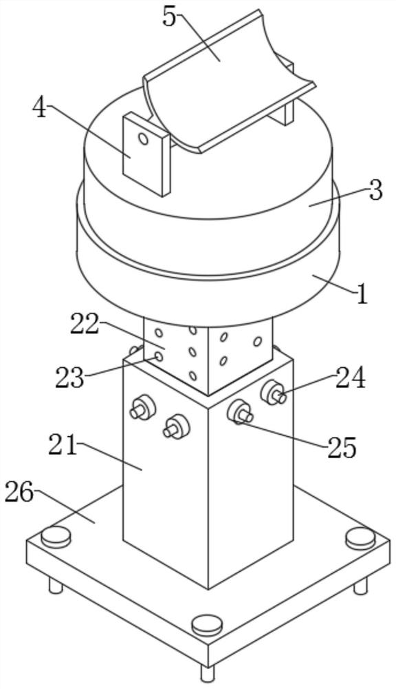
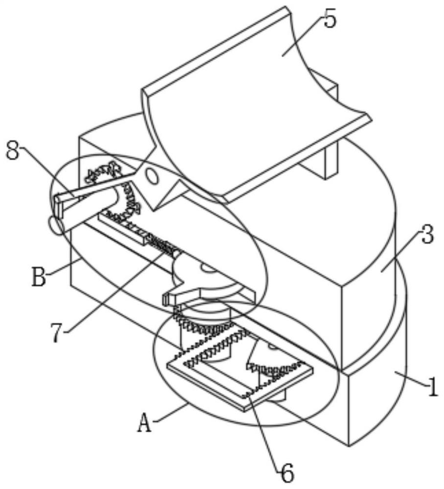
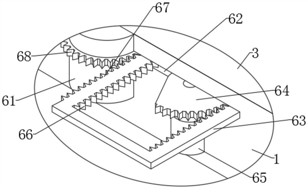
[0029] Example: as Figure 1 to Figure 6 As shown, the present invention provides a radar device with an antenna azimuth turntable, including a fixed base 1, a bottom of the fixed base 1 is installed with an adjustment base 2, a top of the fixed base 1 is rotated to install a rotating base 3, and a top surface of the rotating base 3 is installed Two fixed plates 4 are fixedly installed, the antenna 5 is installed between the fixed plates 4, the rotating mechanism 6 is installed between the fixed base 1 and the rotating base 3, the swing mechanism 5 is installed between the rotating base 3 and the antenna 5, and the swing mechanism 5 and the slewing mechanism 6 are installed Install linkage mechanism 7 between. The installation height of the antenna 5 is adjusted by the adjusting base 2, and the slewing mechanism 6 drives the rotating base 3 to reciprocate, so that the antenna 5 rotates for inspection, avoiding the difficulty of line connection caused by continuous rotation. T...


PUM


Abstract

The invention discloses radar equipment with an antenna azimuth turntable and a use method thereof, and belongs to the technical field of radar, the radar equipment comprises a fixed seat, an adjusting seat is mounted at the bottom of the fixed seat, a rotating seat is rotatably mounted at the top of the fixed seat, two fixed plates are fixedly mounted on the top surface of the rotating seat, and an antenna is mounted between the fixed plates; a swing mechanism is installed between the fixed seat and the rotating seat, a swing mechanism is installed between the rotating seat and the antenna, and a linkage mechanism is installed between the swing mechanism and the swing mechanism. The mounting height of the antenna is adjusted through the adjusting seat, the slewing mechanism drives the rotating seat to rotate in a reciprocating mode, the antenna rotates in a reciprocating mode for inspection, line connection difficulty caused by continuous rotation is avoided, meanwhile, the swing mechanism is driven through the linkage mechanism, the pitch angle of the antenna is synchronously changed, and the purpose of all-directional monitoring is achieved.

Description

technical field [0001] The invention relates to the technical field of radar, in particular to a radar device with an antenna azimuth turntable and a using method thereof. Background technique [0002] Radar, is the transliteration of English Radar, derived from the abbreviation of radio detection and ranging, which means "radio detection and ranging", that is, using radio methods to find targets and determine their spatial positions, radar antennas are often rotated through the azimuth turntable. , so as to achieve the purpose of multi-directional monitoring. However, the current antenna azimuth turntable is continuously rotated in one direction, so the connection line between the antenna and the radar equipment needs to be connected by a rotating electrical connection such as a brush, and the installation method and cost are high. Moreover, the radar antenna can only be rotated and inspected at a fixed pitch angle, and there is a dead angle in monitoring. Therefore, we pro...

Claims


Application Information

Patent Timeline
Patent Type & Authority Applications(China)
IPC IPC(8): G01S7/02
CPCG01S7/02
Inventor 于挺张山梁晨唐国盛易宏伟唐微微
Owner 盐城格跃智能科技有限公司
Why Eureka
Try Eureka