A special mold and production process for concrete electric poles with convenient construction

A production process and concrete technology, applied in the direction of molds, etc., can solve the problems of adjustment, can not save transportation space, affect the erection efficiency of electric poles, etc., and achieve the effect of saving costs, improving the efficiency of opening holes, and accelerating production.

Active Publication Date: 2020-04-10
安徽联众电力科技有限公司
View PDF8 Cites 0 Cited by
  • Summary
  • Abstract
  • Description
  • Claims
  • Application Information

AI Technical Summary

Problems solved by technology

[0004] Although the flange design of the above scheme can ensure faster assembly process and more stable structure after assembly, due to problems such as the structural design of the sectioned pole structure, it is impossible to use a static press to press the pole deep into the ground and erect the pole. During the process, the conventional process of digging, poles, filling and compaction is still required, which greatly affects the efficiency of pole erection; during transportation, although the difficulty of transportation and the length of the transport vehicle can be reduced by segmentation, it cannot save transportation space; In addition, once the concrete pole is erected, on the one hand, the height of the concrete pole after erection cannot be reasonably adjusted according to the national standard requirements of the lowest point of sag of the erected wire, unless the concrete pole is pulled out and the concrete pole is readjusted. The height of the ground surface and the distance between two concrete poles; on the other hand, when the ground surface at the point where the concrete poles are erected partially sinks, the height can be flexibly changed to ensure that the lowest point of the wire sag meets the national standard requirements

Method used


Image

  • A special mold and production process for concrete electric poles with convenient construction
  • A special mold and production process for concrete electric poles with convenient construction
  • A special mold and production process for concrete electric poles with convenient construction

Examples


Embodiment 1

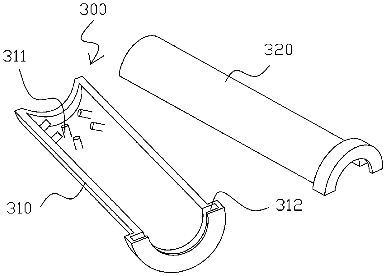
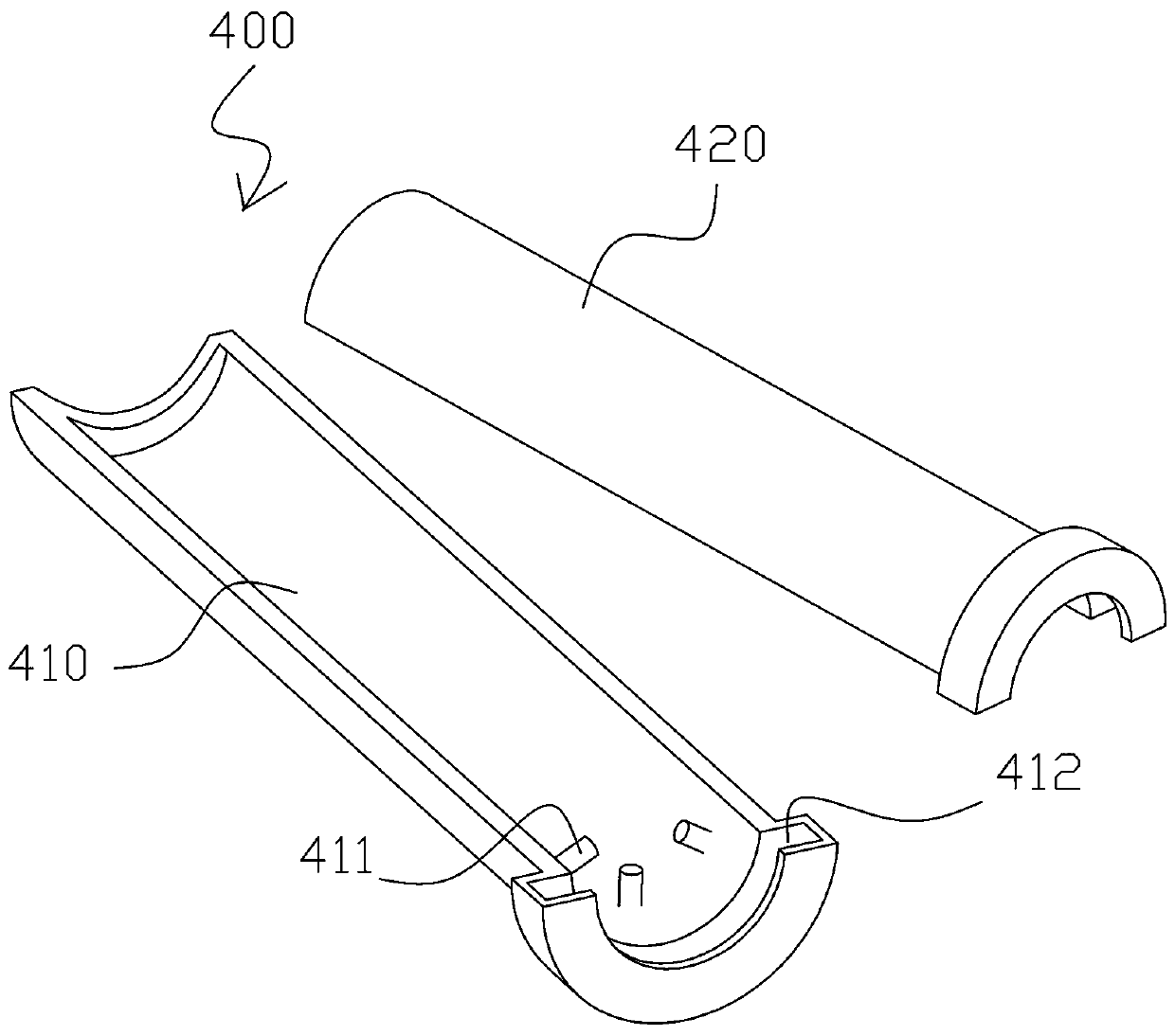
[0076] Such as figure 1 , figure 2 As shown, this embodiment provides a special mold for concrete poles that is convenient for construction, including an upper pole steel mold 300 and a lower pole steel mold 400; the upper pole steel mold 300 includes a coaxially arranged upper pole first half membrane 310 and the second half-membrane 320 of the upper rod, the upper end of the first half-membrane 310 of the upper rod and the upper end of the second half-membrane 320 of the upper rod are formed with an upper rod concave cavity 312 protruding outwards in a semi-circular shape, the upper rod The inner surface of the lower end of the first half-membrane 310 and the inner surface of the lower end of the second half-membrane 320 of the upper rod are equally spaced along the length direction to form multiple groups of protruding column groups, and each of the protruding column groups includes several radially protruding coils. The upper rod protruding pillars 311 distributed at int...

Embodiment 2

[0084] This embodiment provides a production process for a convenient concrete pole, which is produced using the mold described in Embodiment 1, including the following steps:

[0085] S1: Use the upper rod production line to prepare the upper rod through the upper rod steel mold 300; on the upper rod production line, select the corresponding upper rod steel mold 300 according to the size and taper of the proposed upper rod to prepare the upper rod;

[0086] S2: Using the lower rod production line to prepare the lower rod with a hollow inner cavity through the lower rod steel mold 400; on the lower rod production line, select the corresponding lower rod steel mold 400 according to the size and taper of the proposed lower rod to prepare the lower rod;

[0087] S3: Using an assembly production line to place the upper pole into the hollow inner cavity of the lower pole to obtain a finished electric pole.

[0088] In the above design, by dividing the production preparation of the ...

Embodiment 3

[0091] The difference between this embodiment and embodiment 2 is that the step S2 includes the following steps:

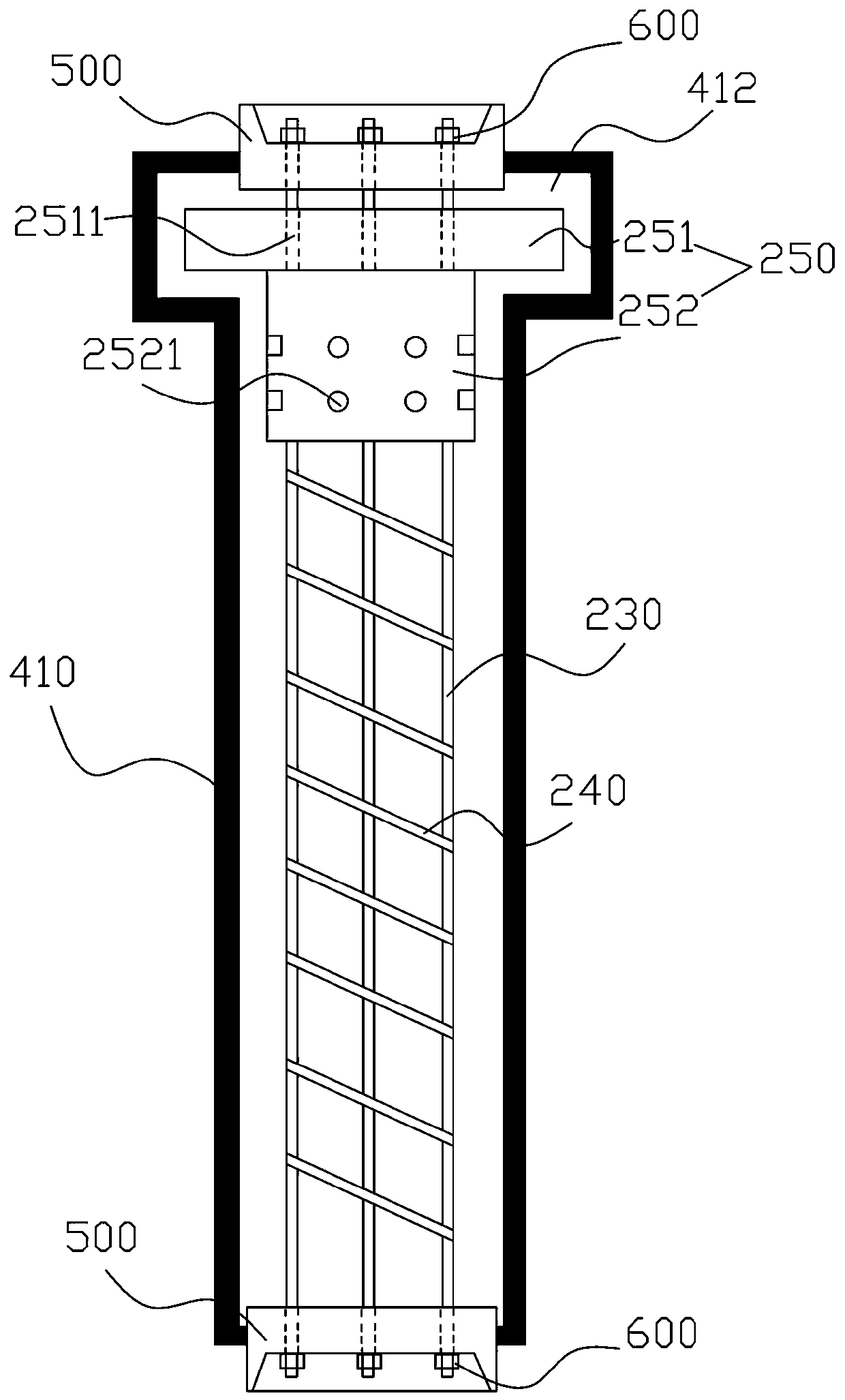
[0092] S21: Prepare and fix the lower rod steel skeleton in the first half membrane 410 of the lower rod;

[0093] S22: Pour concrete; put a preset amount of concrete slurry into the first half-membrane 410 of the lower rod on which the reinforcement skeleton of the lower rod is fixed; specifically, use a feeding device to move along the lower rod at a certain speed The first half-membrane 410 moves in the length direction, while releasing the concrete slurry and inserting it into the first half-membrane 410 of the lower rod;

[0094] S23: 400 lower rod steel mold clamping;

[0095] S24: stretching and centrifugation;

[0096] S25: Curing; put the lower rod steel film 400 after centrifugation into the steam pool for steam curing according to a given process curve. The steam curing process includes four stages of static curing-heating-constant temperature-cooling...


PUM


Abstract

The invention relates to the technical field of concrete electric poles, and discloses a special die for a concrete electric pole convenient to construct and a production process. The die comprises anupper pole steel die and a lower pole steel die, wherein the upper pole steel die comprises an upper pole concave cavity and an upper pole protruding column, and the lower pole steel die comprises alower pole concave cavity and a lower pole protruding column. The production process comprises the following steps of: producing an upper pole through the upper pole steel die by using an upper pole production line, producing a lower pole with a hollow inner cavity through the lower pole steel die by using a lower pole production line, and placing the upper pole into the hollow inner cavity of thelower pole by utilizing an assembling production line to obtain a finished electric pole product. The special die can be used to reliably, conveniently and efficiently produce the concrete electric pole with the advantages of being flexible in height adjustment, convenient to construct and maintain and high in structural strength and saving transportation space.

Description

technical field [0001] The invention relates to the technical field of concrete electric poles, in particular to a special mold for concrete electric poles with convenient construction and a production process. Background technique [0002] In order to facilitate the processing and transportation of concrete poles, concrete pole manufacturers generally process longer concrete poles in sections for transportation and on-site assembly. The butt joint of the steel ring is fixed by welding, but it is prone to misalignment, welding deformation, and pole end bending after assembly, and the welded part of the pole is easy to rust and rot after long-term use, and the durability is not strong and there is drop In addition, there are many construction tools that need to be carried, which is not conducive to carrying and on-site deployment. The construction steps are also complicated and cumbersome, which is not conducive to high-efficiency construction on site; [0003] The patent do...

Claims


Application Information

Patent Timeline
Patent Type & Authority Patents(China)
IPC IPC(8): B28B21/82
CPCB28B21/82
Inventor 丁其友
Owner 安徽联众电力科技有限公司
Why Eureka
Try Eureka