Flexible direct current converter transformer

A converter transformer and flexible DC technology, applied in the field of transformers, can solve problems such as inconvenient maintenance and restricted outlet structure of flexible DC converter transformers, and achieve the effects of facilitating later maintenance, ensuring structural stability, and saving costs

Pending Publication Date: 2022-07-12
GUANGZHOU POWER SUPPLY BUREAU GUANGDONG POWER GRID CO LTD
0 Cites 0 Cited by

AI-Extracted Technical Summary

Problems solved by technology

[0004] The purpose of the present invention is to provide a flexible DC converter transformer to solve the problem ...

Method used

Based on above structure, the first valve side sleeve pipe 81, the second valve side sleeve pipe 82, the first network side sleeve pipe 83, the second network side sleeve pipe 84 are all located on the long axis side of casing 1, and It is on the same side, which is suitable for the space layout of the current indoor converter transformer, and is convenient for entering lines on each side of the transformer, saving the cost of the wall bushing, and facilitating later maintenance; in addition, the first valve side bushing 81 and the second valve side bushing 82. The first grid-side bushing 83 and the second grid-side bushing 84 are all extended out of the box body 1, and are respectively arranged at the four corners of the side of the long axis of the box body 1, thereby ensuring a reliable insulation distance on each side of the transformer 100, The wall bushing 8 on the grid side and valve side is saved, and the overall height of the flexible straight transformer is equivalent to that of the grid side and valve side bushings, which is conducive to the indoor layout of the transformer, avoids the crossing of the grid side and valve side, and is convenient Maintenance of bus inlet, valve side outlet and converter transformer.
Based on the above-mentioned structure, the first valve side sleeve pipe 81, the second valve side sleeve pipe 82, the first network side sleeve pipe 83, and the second network side sleeve pipe 84 of the transformer in the present embodiment are arranged in the transformer box 1 The side of the long axis of the current transformer 100 is on the same side, and the outlet structure of the existing transformer 100 mostly adopts the top outlet, the short axis side outlet or both sides outlet, but because the flexible DC converter transformer 100 is affected by DC bias and high-order harmonic current It is easy to cause vibration and noise. Most of the flexible DC converter transformers 100 are installed indoors. When the top outlet is used, the height of the transformer is determined by the height of the box 1 and the bushing 8, resulting in a flexible DC converter. The upper space requirement of the transformer room is too large; when the side outlet of the short shaft is used, the width of the flexible DC converter transformer room is determined by the width of the box body 1 and the extension seat of the bushing 8, and the room space will be very cramped, which is not conducive to operation and maintenance. When the DC converter transformer 100 is removed, it is necessary to dismantle the grid-side GIS branch bus, grid-side EVT, and grid-side surge arrester equipment. The process is compl...

Abstract

The invention relates to the technical field of transformers, and discloses a flexible direct current converter transformer which comprises a box body and a transformer body arranged in the box body, the transformer body is sleeved with a plurality of coil windings, and outgoing lines of the windings are led out from the side face of a long axis of the box body and on the same side. The novel flexible direct current converter transformer winding wire outlet structure is suitable for current all-indoor converter transformer space arrangement, wire inlet of all sides of the transformer is facilitated, the cost of a wall bushing is saved, later maintenance is facilitated, and meanwhile the stability of the wire outlet structure can be guaranteed through the arranged supporting assembly.

Application Domain

Technology Topic

Image

  • Flexible direct current converter transformer
  • Flexible direct current converter transformer
  • Flexible direct current converter transformer

Examples

  • Experimental program(1)

Example Embodiment

[0032] The technical solutions in the embodiments of the present application will be clearly and completely described below with reference to the drawings in the embodiments of the present application. Obviously, the described embodiments are only a part of the embodiments of the present application, rather than all the embodiments.
[0033] It is to be understood that in the description of this application, the terms "center", "upper", "lower", "left", "right", "top", "bottom", "inner", "outer", etc. indicate The orientation or positional relationship is based on the orientation or positional relationship shown in the accompanying drawings, which is only for the convenience of describing the present application and simplifying the description, rather than indicating or implying that the referred device or element must have a specific orientation or be constructed in a specific orientation. and operation, and therefore should not be construed as a limitation on this application. The terms "first" and "second" are only used for descriptive purposes, and should not be construed as indicating or implying relative importance or implying the number of indicated technical features, that is, defined with "first", "first" and "second". A feature of "two" may expressly or implicitly include one or more of that feature.
[0034] It should be noted that, in the description of this application, unless otherwise expressly specified and limited, the terms "installed", "connected" and "connected" should be understood in a broad sense, for example, it may be a fixed connection or a detachable connection Connection, or integral connection; can be mechanical connection, can also be electrical connection; can be directly connected, can also be indirectly connected through an intermediate medium, can be internal communication between two elements. For those of ordinary skill in the art, the specific meanings of the above terms in this application can be understood in specific situations.
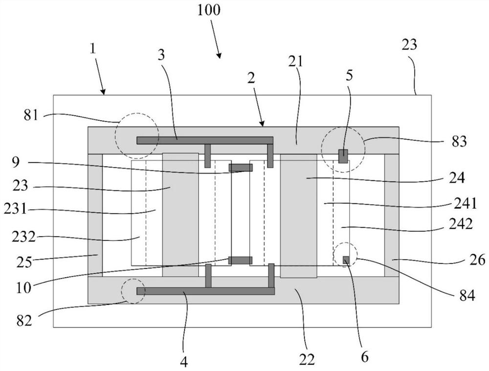
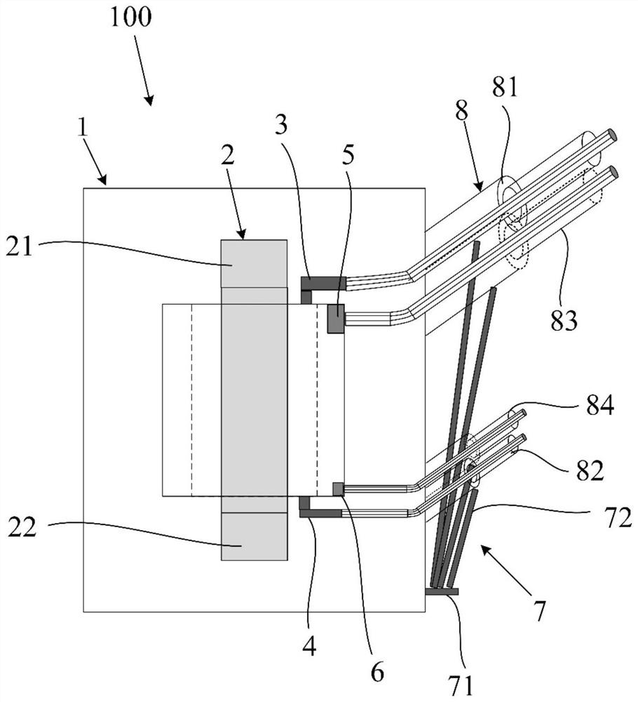
[0035] like figure 1 , 2 As shown, the embodiment of the present invention provides a flexible DC converter transformer 100, which includes a box body 1 and a transformer body 2 arranged in the box body 1, and a plurality of coil windings are sheathed on the transformer body 2. Preferably, The coil windings are all outgoing wires from the end; the coil windings include valve-side windings and grid-side windings; the lead-out wires at the head ends of the valve-side windings are connected in parallel to the first lead-out wire 3, and the first lead-out wire 3 is connected from the The side of the long axis of the box body 1 leads out of the box body 1, the outer circumference of the first lead wire 3 is sleeved with a first valve side bushing 81, and the lead wire of each valve side winding end is connected in parallel to the second valve side. Lead wire 4, the second lead wire 4 is led out of the box 1 from the same side of the first lead wire 3, and a second valve side sleeve 82 is sleeved on the outer periphery of the second lead wire 4; The head ends of the mesh side windings are connected in series with each other, and are led out of the box from the same side of the first lead wire 3 through the third lead wire 5. The outer circumference of the third lead wire 5 is sleeved with a first lead wire. The mesh side bushings 83, the ends of the mesh side windings are connected in series with each other, and are led out of the box 1 from the same side of the first lead wire 3 through the fourth lead wire 6. The outer periphery is sleeved with a second mesh side sleeve 84 .
[0036] Based on the above structure, in this embodiment, the first valve side bushing 81 , the second valve side bushing 82 , the first grid side bushing 83 , and the second grid side bushing 84 of the transformer are arranged on the long axis of the transformer box 1 . On the side, and on the same side, the outlet structure of the existing transformer 100 mostly adopts the top outlet, the short axis side outlet or the two sides outlet, but because the flexible DC converter transformer 100 is affected by DC bias and higher harmonic current, it is easy to Causes vibration and noise. Most of the flexible DC converter transformers 100 are installed indoors. When the top outlet is used, the height of the transformer is determined by the height of the box 1 and the bushing 8, resulting in a flexible DC converter transformer room. The upper space requirement is too large; when the short-shaft side outlet is used, the width of the flexible DC converter transformer room is determined by the width of the box 1 and the extension seat of the casing 8, and the room space will be very cramped, which is not conducive to operation and maintenance. When the transformer 100 is removed, it is necessary to remove the grid-side GIS branch bus, grid-side EVT, and grid-side arrester equipment, which is a complex process and a tedious process; when using two-side outgoing lines, both sides are out of the bushing 8 side, and the flexible DC commutation cannot be opened. The door of the transformer room, the flexible DC converter transformer 100 needs to be removed from the grid side wall of the flexible DC converter transformer room. Therefore, the arrangement of the outlet structure of the winding bushing 8 is subject to certain restrictions, and the maintenance of the above-mentioned bushing 8 outlet structure is also inconvenient. . The embodiment of the present invention provides a flexible DC converter transformer 100 winding stable outlet structure on the same side, the grid-side winding and the valve-side winding both use the air bushing 8 to protrude from the same side, and there is no need to add additional fractures of the air bushing 8, saving energy Wall bushings for grid-side windings and valve-side windings, the overall height of the flexible DC converter transformer 100 is equivalent to the oil-gas bushing on the grid-side valve side, which is beneficial to the arrangement of flexible DC converter transformer rooms and avoids grid-side windings It is convenient for maintenance and inspection if it crosses the connection line of the valve side winding.
[0037] It can be understood that the bushing 8 is the main insulating device outside the box 1, and the lead wires of the transformer winding must pass through the bushing to insulate between the lead wires and between the lead wires and the transformer shell, and at the same time act as a fixed support to lead out. the role of the line.
[0038] Preferably, as figure 1 As shown, the transformer body 2 provided in this embodiment is a single-phase double-winding structure, including an upper iron yoke 21 , a lower iron yoke 22 , and a first iron core 23 disposed between the upper iron yoke 21 and the lower iron yoke 22 . and the second iron core 24 and the first side pillars 25 and the second side pillars 26 on both sides of the iron core; the outer periphery of each iron core is sequentially sheathed with the valve side winding and the mesh side winding, that is, the valve side winding The first iron core 23 is sheathed with the first valve side winding 231, the first mesh side winding 232, and the second iron core 24. A second valve-side winding 241 and a second grid-side winding 242 are sequentially sheathed on the top.
[0039] It should be noted that the transformer body 2 is a closed structure, in which the coil winding part is called an iron core, and the upper iron yoke 21 , the lower iron yoke 22 , the first side column 25 and the second side column 26 do not cover the coil windings, and are only used for The magnetic flux loop acts as a closed magnetic circuit.
[0040] Preferably, the lead wire of the head end of the first valve side winding 231 and the lead wire of the head end of the second valve side winding 241 are connected in parallel to the first lead wire 3 , and the first lead wire 3 extends to the side of the long axis of the casing 1 . The first valve side bushing 81 is sleeved on the outer periphery of the first lead wire 3; the lead wire at the end of the first valve side winding 231 and the end of the second valve side winding 241 The lead wire is connected in parallel to the second lead wire 4. The second lead wire 4 extends to one end of the side surface of the long axis of the box body 1, and is led out of the box body 1. The outer circumference of the second lead wire is sleeved with a second lead wire. The valve side bushing 82, the first lead wire 3 and the second lead wire 4 are respectively arranged above and below the iron core, the first valve side bushing 81 and the second valve side bushing 82 are inclined upward through the wall .
[0041] Preferably, the head end of the first line side winding 232 is connected in series with the head end of the second line side winding 242 through the first connector 9 , and is connected to the side of the long axis of the box 1 through the third lead wire 5 . The other end of the first grid side winding 232 is connected in series with the end of the second grid side winding 242 through the second connector 10 , and is extended from the box 1 through the fourth lead wire 6 The other end of the shaft side is led out, wherein the third lead wire 5 is led out of the box 1 from the outside of the second wire side winding 242, the outer circumference of the third lead wire 5 is sleeved with a first wire side sleeve 83, and the fourth lead wire 5 is led out of the box 1. The wire 6 is led out of the box 1 from the outside of the second wire side winding 242, and the second wire sleeve 84 is sleeved on the outer circumference of the fourth wire 6. Since the third wire 5 and the fourth wire 6 are respectively arranged in the The upper and lower parts of the iron core, therefore, the first mesh side sleeve 83 and the second mesh side sleeve 84 are respectively arranged at the upper and lower ends of the second iron core 24, and the first mesh side sleeve 83 and the second mesh side sleeve 84. 84 are inclined upward relative to the box body 1 .
[0042] Based on the above structure, the first valve side bushing 81 , the second valve side bushing 82 , the first mesh side bushing 83 , and the second mesh side bushing 84 are all provided on the long axis side of the box body 1 , and are on the same side. , it is suitable for the current all-indoor converter transformer space layout, and it is convenient for entering wires on all sides of the transformer, saving the cost of through-wall bushings, and facilitating later maintenance; in addition, the first valve side bushing 81, the second valve side bushing 82, the The first grid-side bushing 83 and the second grid-side bushing 84 extend out of the box 1 and are located at the four corners of the side surface of the long axis of the box 1, thereby ensuring a reliable insulation distance on each side of the transformer 100, saving grid The overall height of the wall bushing 8 on the side and the valve side is equivalent to that of the grid side and valve side bushings, which is beneficial to the indoor arrangement of the transformer, avoids the crossover of the grid side and the valve side, and facilitates the entry of the busbar. , valve side outlet and converter maintenance.
[0043] Preferably, the first valve side bushing 81, the second valve side bushing 82, the first mesh side bushing 83, and the second mesh side bushing 84 are dry high pressure bushings, and the dry type high pressure bushings are heavy in weight. It has the advantages of light weight, stable electrical performance, high mechanical strength and good stain resistance.
[0044] In order to provide reliable external support for the casing, preferably, such as figure 2 , 3 As shown, in this embodiment, the box body 1 is provided with a support assembly 7 that assists in supporting the sleeve 8, thereby ensuring the structural stability of the sleeve 8; further preferably, the support assembly 7 is provided in the box body 1. The lower end is located on the same side of the first lead wire 3. The support assembly 7 includes a base 71 and a plurality of support rods 72 rotatably connected to the base 71. Casing 8.
[0045] Preferably, the support assembly 7 further includes a ball head, the upper surface of the base 71 is provided with a ball bowl in which the ball head 73 is embedded, one end of the ball head 73 is embedded in the ball bowl, and the other end is embedded with the ball head 73 . The lower end of the support rod 72 is fixedly connected to realize the rotation connection of the support rod 72 with the base 71 along with the rotation of the ball head 73 in the ball bowl, so that the support rod 72 can be adjusted according to the different positions of the sleeve 8 Angle.
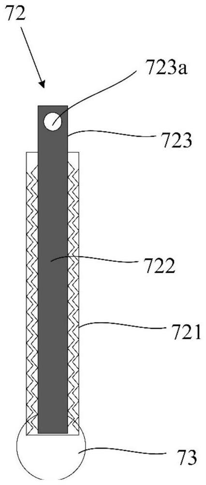
[0046] Preferably, as image 3 As shown, the support rod 72 includes a sleeve 721 and a threaded rod 722 disposed in the sleeve 721. The sleeve 721 is internally threaded, and the sleeve 721 is screwed with the threaded rod 722 through threads. In cooperation, the threaded rod 722 is rotated and retracted in the sleeve 721 to adjust the length of the support rod 72 to meet the support requirements of the sleeves 8 of different heights.
[0047] Further preferably, the length of the threaded rod 722 is greater than the length of the sleeve 721, and the protrusion 723 of the threaded rod 722 protruding from the sleeve 721 is provided with a threaded hole 723a connected to the sleeve 8. Specifically, when the support rod 72 When in contact with the bottom of the sleeve 8 , a screw is passed through the threaded hole 723 a and connected to the bottom of the sleeve 8 to realize the fixed support of the support assembly 7 and the sleeve 8 .
[0048] To sum up, the embodiment of the present invention provides a flexible DC converter transformer 100. By adopting a new winding outlet structure of the flexible DC converter transformer 100, it is suitable for the current all-indoor space layout of converter transformers, and is convenient for entering the transformer 100 at each side. It can save the cost of through-wall casing and facilitate later maintenance. The supporting assembly 7 provided at the same time can ensure the structural stability of the sleeve 8 .
[0049] The above are only the preferred embodiments of the present invention. It should be pointed out that for those skilled in the art, without departing from the technical principle of the present invention, several improvements and substitutions can be made. These improvements and substitutions It should also be regarded as the protection scope of the present invention.

PUM

no PUM

Description & Claims & Application Information

We can also present the details of the Description, Claims and Application information to help users get a comprehensive understanding of the technical details of the patent, such as background art, summary of invention, brief description of drawings, description of embodiments, and other original content. On the other hand, users can also determine the specific scope of protection of the technology through the list of claims; as well as understand the changes in the life cycle of the technology with the presentation of the patent timeline. Login to view more.

Similar technology patents

Thin walled, two component cartridge casing

InactiveUS20070214992A1Eliminate operationLow costCartridge ammunitionCarbon steelThin walled
Owner:TECH CORPORATION CO LTD

Classification and recommendation of technical efficacy words

  • Low cost
  • Easy to maintain later

Semiconductor device

InactiveUS6975142B2Low costReduce manufacturing stepsTransistorSolid-state devicesVoltage amplitudeSemiconductor
Owner:SEMICON ENERGY LAB CO LTD

Community data system

Owner:QINGDAO PENGHAI SOFT CO LTD
Why Eureka
Try Eureka