Radiating fin group with improved structure

A heat dissipation fin group and heat dissipation single-chip technology, which is applied in the direction of cooling/ventilation/heating transformation, can solve the problems of low heat dissipation efficiency, difficulty in meeting heat dissipation requirements, and high production costs, and achieve high heat dissipation efficiency, high efficiency, and uniform heat dissipation. The effect of simple structure

Pending Publication Date: 2022-07-12
KUNSHAN ANIL PRECISE METAL
View PDF0 Cites 0 Cited by
  • Summary
  • Abstract
  • Description
  • Claims
  • Application Information

AI Technical Summary

Problems solved by technology

[0002] Using heat sinks to increase the heat dissipation area is the most common way for heat sinks. At present, heat sinks are structures that are sequentially buckled together by multiple heat sinks. A heat dissipation channel for airflow is formed between the heat sinks. At present, heat dissipation in heat sinks Most of the single chips adopt the same structure, and their heat dissipation efficiency is low. With the increase of heat density in electronic products, the need for heat dissipation is increasing. At present, it is difficult for the common heat sink group to meet the heat dissipation requirements. In order to improve the traditional heat sink At present, there are various heat sink group structures with complex structures, but due to their complex structures, they are difficult to manufacture, high in production costs, poor in use stability, and prone to failure.

Method used


Image

  • Radiating fin group with improved structure
  • Radiating fin group with improved structure
  • Radiating fin group with improved structure

Examples


Embodiment

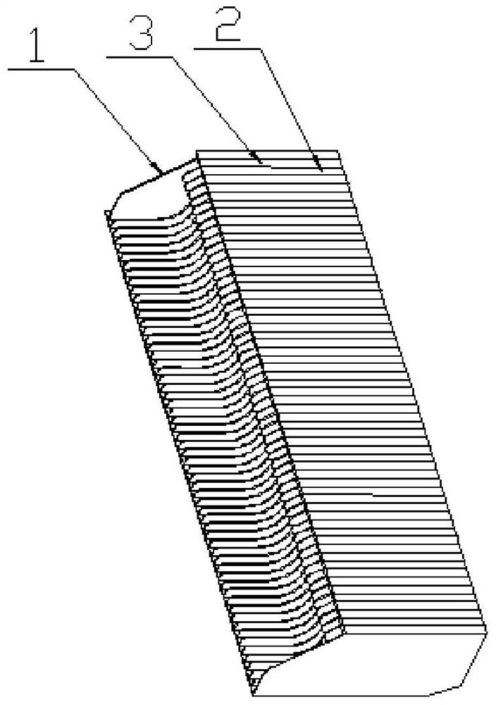
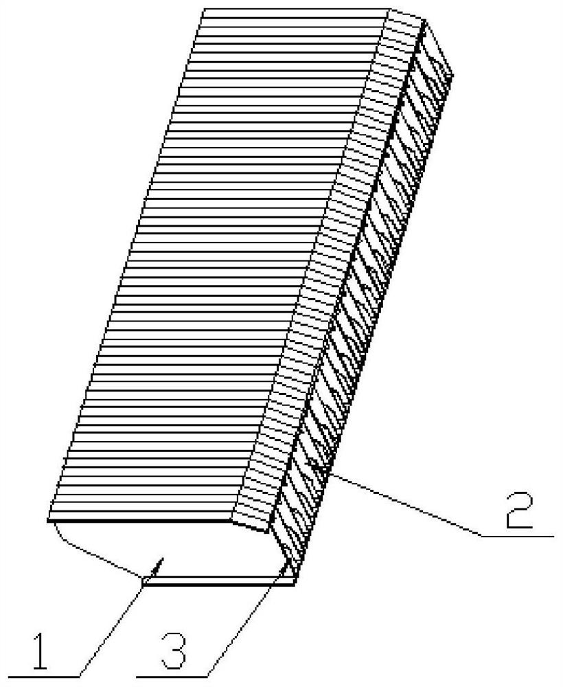
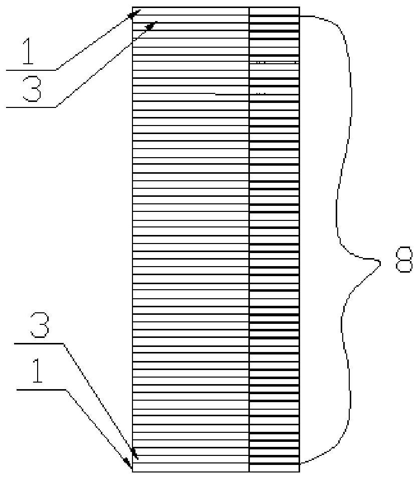
[0024] Embodiment: A heat dissipation fin group with improved structure, which is characterized by: comprising a first heat dissipation single piece 1, a second heat dissipation single piece 2 and a third heat dissipation single piece 3 in a U-shaped structure, and a plurality of second heat dissipation single pieces. 2 and the third heat-dissipating single piece 3 are alternately arranged and connected to form an intermediate heat-dissipating single-piece group 8 . The second heat dissipation single sheet 2 and the third heat dissipation single sheet 3 are formed with a first U-shaped opening 4 at one end of the bottom surface of the U-shaped structure.

[0025] The first heat dissipation single piece 1, the second heat dissipation single piece 2 and the third heat dissipation single piece 3 are stacked to form the entire heat dissipation fin group, a heat dissipation channel for airflow is formed between adjacent heat dissipation single pieces, and the heating element is loca...


PUM


Abstract

The invention discloses a heat dissipation fin group with an improved structure, which comprises a first heat dissipation single sheet, a second heat dissipation single sheet and a third heat dissipation single sheet which are of a U-shaped structure, and a plurality of second heat dissipation single sheets and third heat dissipation single sheets are alternately arranged, buckled and connected to form a middle heat dissipation single sheet group. The two first heat dissipation single pieces are located on the two sides of the arrangement direction of the middle heat dissipation single piece set respectively, the first heat dissipation single pieces and the middle heat dissipation single piece set are connected in a buckled mode to form an integrated structure, a first U-shaped opening is formed in one end of the bottom face of the U-shaped structure of each second heat dissipation single piece and one end of the bottom face of the U-shaped structure of each third heat dissipation single piece, and the heat dissipation device is simple and stable in structure and high in heat dissipation efficiency.

Description

technical field [0001] The present invention relates to a radiator, in particular to a heat dissipation fin group with improved structure. Background technique [0002] The use of heat sinks to increase the heat dissipation area is the most common way of radiators. At present, heat sinks are a structure formed by a number of heat sinks that are sequentially buckled. A heat dissipation channel for airflow is formed between the heat sinks. Most of the single chips use the same structure, and their heat dissipation efficiency is low. With the increase of heat generation density in electronic products, the need for heat dissipation is increasing. At present, it is difficult for common heat sink sets to meet the heat dissipation requirements. In order to improve the traditional heat sink The heat dissipation efficiency of the group, there are various complex structure of the heat sink group structure, but due to the complex structure, difficult to manufacture, high production cos...

Claims


Application Information

Patent Timeline
Patent Type & Authority Applications(China)
IPC IPC(8): H05K7/20
CPCH05K7/2039H05K7/20009
Inventor 林志昆
Owner KUNSHAN ANIL PRECISE METAL
Why Eureka
Try Eureka