Coding metasurface antenna array structure based on phase gradient and design method

A technology of antenna array and phase gradient, which is applied in the direction of antenna array, antenna array, antenna, etc. that are powered separately, and can solve the problem of increasing the size of the antenna

Pending Publication Date: 2022-07-15
NANJING UNIV OF AERONAUTICS & ASTRONAUTICS
View PDF0 Cites 0 Cited by
  • Summary
  • Abstract
  • Description
  • Claims
  • Application Information

AI Technical Summary

Problems solved by technology

However, at present, for the stealth design of the phase gradient antenna array, the phase gradient metasurface is loaded around the antenna as an accessory, which not only needs to be designed separately, but also increases the size of the antenna.

Method used


Image

  • Coding metasurface antenna array structure based on phase gradient and design method
  • Coding metasurface antenna array structure based on phase gradient and design method
  • Coding metasurface antenna array structure based on phase gradient and design method

Examples


Embodiment Construction

[0042]The present invention will be further described below in conjunction with the accompanying drawings. Obviously, the described embodiments are some, but not all, embodiments of the present invention. Based on the embodiments of the present invention, all other embodiments obtained by those of ordinary skill in the art without creative efforts shall fall within the protection scope of the present invention.

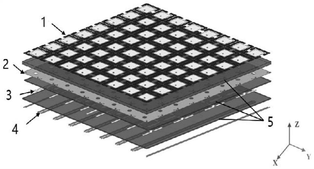
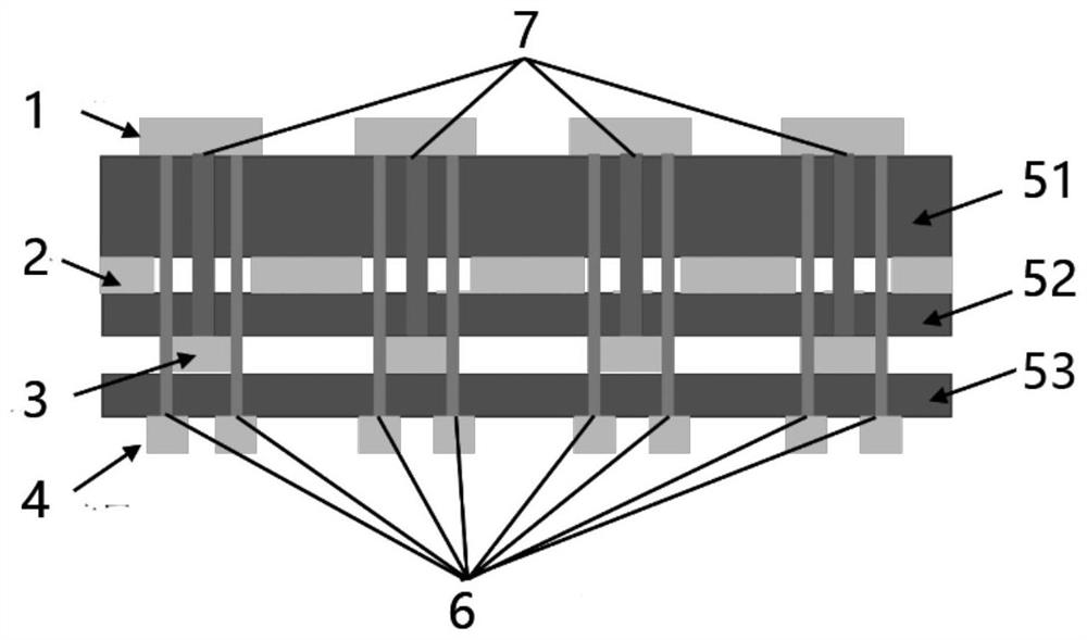
[0043] In this embodiment, an 8*8 metasurface antenna array is used as an example to introduce the specific structure. Figure 1-2 As shown, it includes a metal patch layer 1, a first intermediate dielectric layer 51, a metal floor layer 2, a second intermediate dielectric layer 52, a feeding network layer 3, a third intermediate dielectric layer 53, and a DC Bias network layer 4.

[0044] The metal patch layer 1 includes several rectangular patch units, and the lower surface of each patch unit is connected to the feeding network layer 3 in the vertical direction th...


PUM


Abstract

The invention discloses a coding metasurface antenna array structure based on phase gradient. The coding metasurface antenna array structure comprises a metal patch layer, a first intermediate dielectric layer, a metal floor layer, a second intermediate dielectric layer, a feed network layer, a third intermediate dielectric layer and a direct current bias network layer which are sequentially laminated together, the metal patch layer comprises a plurality of rectangular patch units, and the lower surfaces of the patch units are connected to the feed network layer in the vertical direction through first feed columns; two sides of the first feed column are respectively provided with a second feed column which is connected with the patch unit and the direct current bias network layer; the invention further provides a corresponding design method, so that the cross polarization scattering phase of the designed coding metasurface antenna array structure meets the phase difference of 180 degrees + / -37 degrees under the on-off state of the four diodes, the purpose of hiding the inside and outside of an antenna band can be achieved, and different dynamic scattering effects can be presented.

Description

technical field [0001] The invention relates to the technical field of microwave antenna design, and mainly relates to a phase gradient-based coding metasurface antenna array structure and design method. Background technique [0002] In modern electronic warfare, the stealth performance of combat platforms such as aircraft, rockets, and ships often directly affects their combat capability and survivability. Through various means, the detectable information characteristics of one's own targets can be changed, and the enemy's target can be changed to the greatest extent possible. The device cannot detect or even mistakenly identify other targets to achieve the purpose of "concealing the true and showing the false". [0003] At present, most of the stealth designs for antenna arrays use passive cancellation technology, or load a frequency-selective surface radome for filtering, or load a metasurface structure around the antenna / floor for wave absorption / phase cancellation... Su...

Claims


Application Information

Patent Timeline
Patent Type & Authority Applications(China)
IPC IPC(8): H01Q21/06H01Q21/00H01Q23/00H01Q15/00G06F30/20G06F30/10
CPCH01Q21/065H01Q21/0087H01Q21/0006H01Q23/00H01Q15/0086H01Q15/0046H01Q15/002G06F30/20G06F30/10
Inventor 马贝贝陈妍何小祥杨阳陈艺薇
Owner NANJING UNIV OF AERONAUTICS & ASTRONAUTICS
Why Eureka
Try Eureka