Device for a microactuator, and microactuator equipped with such a device

A micro-actuator and actuator technology, applied in the field of micro-actuator devices and micro-technical fixture devices, can solve problems such as high asymmetry, complexity, and vulnerability, and achieve easy manufacturing and a small number of parts. Effect

Pending Publication Date: 2022-07-15
佩尔西皮奥罗机器人公司
View PDF0 Cites 0 Cited by
  • Summary
  • Abstract
  • Description
  • Claims
  • Application Information

AI Technical Summary

Problems solved by technology

This amplifying structure has a larger amplification factor than other known amplifying structures, but at the expense of a high degree of asymmetry
Additionally, its large number of parts makes it complex, fragile and unusable

Method used


Image

  • Device for a microactuator, and microactuator equipped with such a device
  • Device for a microactuator, and microactuator equipped with such a device
  • Device for a microactuator, and microactuator equipped with such a device

Examples


Embodiment Construction

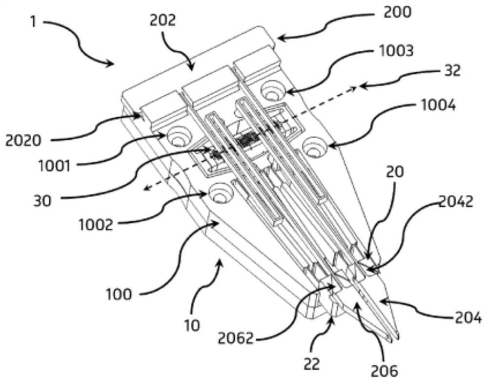
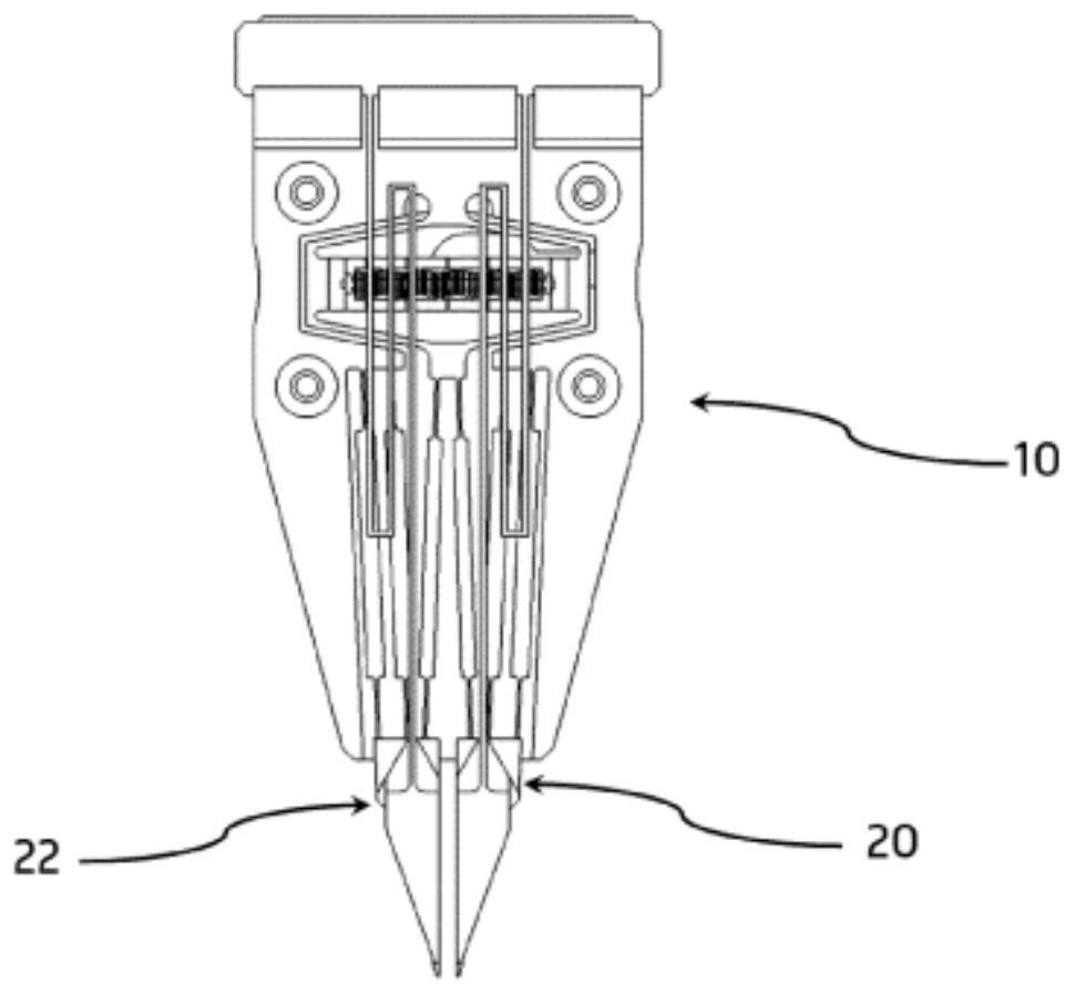
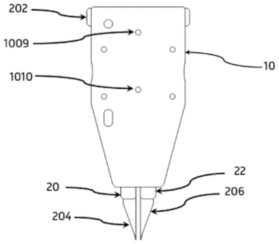
[0043] reference now Figure 1 to Figure 6 .

[0044] The microactuator 1 includes a base 10 , two terminal members 20 and 22 , and an actuator 30 that actuates the terminal members 20 and 22 .

[0045] In one embodiment, the microactuator 1 is a microtechnology clamp and the terminal members are gripping members, such as finger carriers, each of which can receive a finger. The actuator 30 can actuate the finger carriers 20 and 22 in order to perform grasping by the microactuator 1 .

[0046] The finger carriers 20, 22 can receive respective fingers to form a microtechnology fixture. In one embodiment, the microactuator 1 comprises an end piece 200 mounted on the base 10, comprising a support piece 202 and two fingers 204 and 206 connected to the support piece 202 by corresponding flexible connecting elements 2040, 2060 , such as described in the applicant's patent EP2718066. Each finger 204, 206 includes a respective fastening base 2042, 2062 by means of which the finger ...


PUM


Abstract

A device for a microactuator includes a body (110), two terminal members (20, 22) joined to the body (110) with joints (136, 138), located on one side of the body (110), and two deformable bowl-shaped walls (120, 122) facing each other. The walls (120, 122) are configured to receive an actuator, two respective first edges (1202, 1222) of the walls (120, 122) on one side are fixed (1264) to the body (110), and two respective second edges (1204) of the walls (120, 122) on the other side are continuously moved under the action of the actuator to a deformation of the walls (120, 122). The movement is transmitted by two arms (132, 134) terminating in two respective terminal members (20, 22).

Description

technical field [0001] The present invention relates to the field of devices for microactuators, and in particular devices for microtechnical grips. Background technique [0002] Microactuators are mechanical devices capable of producing motion over a very short distance (hereafter referred to as the actuator stroke). In particular, microtech grips are microactuators that perform grasping of small objects by means of fingers that move along the actuator stroke. These fingers are typically mounted on a finger carrier (also referred to as a terminal member). [0003] Microtech grips, and more generally microactuators, are most often driven by piezoelectric actuators that are capable of expanding and contracting, or deforming, in response to an electric field. Piezoelectric actuators generally have the form of stacks in the stacking direction. The stack deforms longitudinally, controlled by an electric field passing through it over its length. This controlled deformation al...

Claims


Application Information

Patent Timeline
IPC IPC(8): B25J7/00B25J9/00
CPCB25J7/00B25J9/0015
Inventor D·赫里班
Owner 佩尔西皮奥罗机器人公司
Why Eureka
Try Eureka