Supercharge Your Innovation With Domain-Expert AI Agents!

Double-magnetic driving system for optical-mechanical system of electronic equipment

A drive system and dual-drive technology, applied in electric components, propulsion systems, optics, etc., can solve problems affecting image resolution, etc.

Pending Publication Date: 2022-07-19
HUAWEI TECH CO LTD
View PDF6 Cites 0 Cited by
  • Summary
  • Abstract
  • Description
  • Claims
  • Application Information

AI Technical Summary

Problems solved by technology

[0004] Therefore, the imaging zoom of portable electronic devices is mostly digital zoom, which unfortunately affects the resolution of the image captured with the camera

Method used


Image

  • Double-magnetic driving system for optical-mechanical system of electronic equipment
  • Double-magnetic driving system for optical-mechanical system of electronic equipment
  • Double-magnetic driving system for optical-mechanical system of electronic equipment

Examples


Embodiment Construction

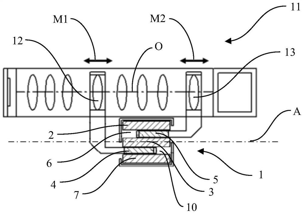
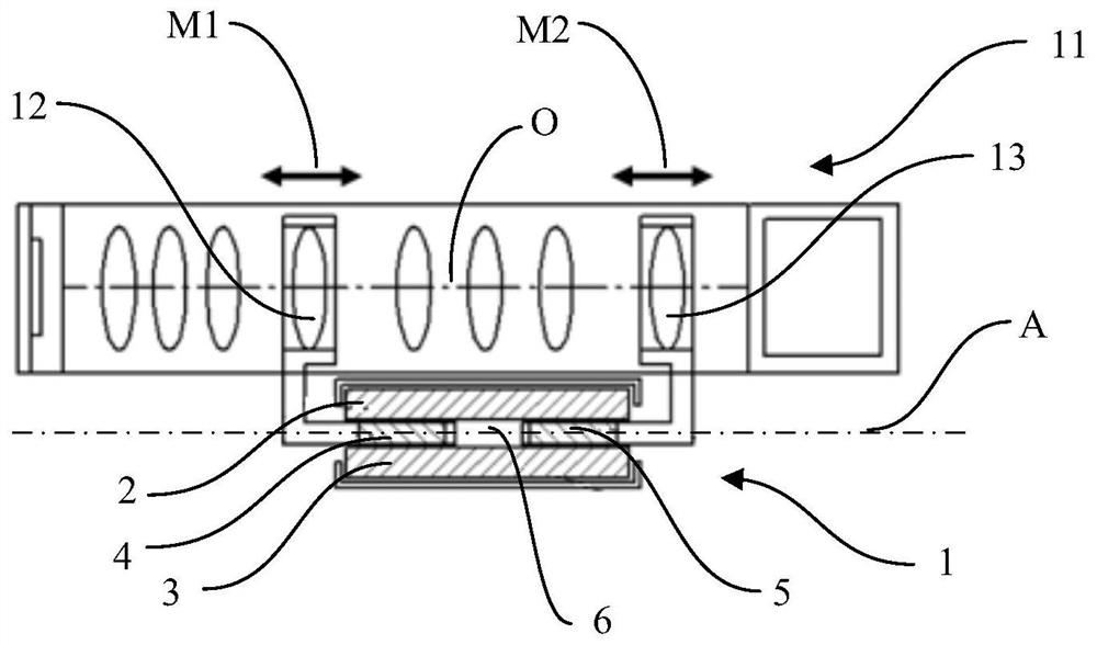
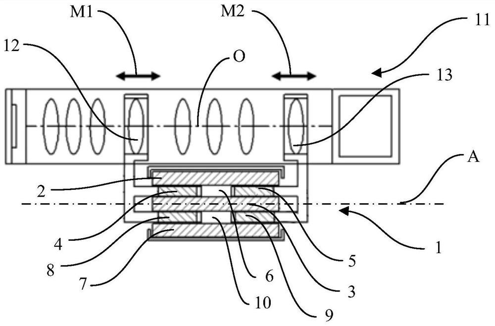
[0032] The invention relates to a dual drive system 1 with a common drive shaft A. The drive system 1 includes at least a first magnet 2 , a second magnet 3 , a first coil 4 and a second coil 5 . The first magnet 2 , the second magnet 3 , the first coil 4 and the second coil 5 are arranged in a direction perpendicular to the drive axis A in an at least partially overlapping manner.

[0033] The drive system 1 operates by: operating the current in the first coil 4, which produces a first movement M1 along the drive axis A; operating the current in the second coil 5, so The current produces a second movement M2 along the drive axis A. The first movement M1 and the second movement M2 are independent of each other. The first movement M1 and the second movement M2 may be generated simultaneously. Further, the first movement M1 and the second movement M2 may be generated in the same direction of the drive axis A and / or in opposite directions of the drive axis A.

[0034] Figure ...


PUM


Abstract

A dual drive system (1) has a drive shaft (A) and comprises a first magnet (2), a second magnet (3), a first coil (4) and a second coil (5). The first magnet (2), the second magnet (3), the first coil (4) and the second coil (5) are arranged in an at least partially overlapping manner in a direction perpendicular to the drive axis (A). Operating the current in the first coil (4) results in a first movement (M1) along the drive axis (A), and operating the current in the second coil (5) results in a second movement (M2) along the drive axis (A). The first movement (M1) and the second movement (M2) are independent of each other. By overlapping the coils and the magnets of the dual drive system, a very compact solution is provided that facilitates the appearance of an opto-mechanical system and an electronic device in which the opto-mechanical system is to be arranged.

Description

technical field [0001] The present invention relates to a dual drive system with a drive shaft comprising magnets and coils. Background technique [0002] There are several difficulties in opto-mechanical systems for portable electronic devices. Preferably, an electronic device such as a mobile phone has an external dimension as small as possible, while an optomechanical system requires a certain dimension in order to provide sufficiently good image definition, spatial frequency, sensitivity, and the like. [0003] Conventional optical zoom cameras typically include two moving lens groups, one for focus and one for zoom, which utilize separate drivers, such as voice coil drivers. These two drivers are separate units that take up some volume and affect the appearance of the camera module. In particular, optomechanical systems including deformable lenses that require mechanical deformation take up a large space because high deformation forces of hundreds of milliNewtons are ...

Claims


Application Information

Patent Timeline
Patent Type & Authority Applications(China)
IPC IPC(8): G02B7/02G02B7/10G02B15/20H02K41/02G02B13/00
CPCG02B7/102G02B7/021G02B15/20G02B13/009H02K41/0356H02K16/00
Inventor 马科·埃罗马基
Owner HUAWEI TECH CO LTD
Features
  • R&D
  • Intellectual Property
  • Life Sciences
  • Materials
  • Tech Scout
  • Unparalleled Data Quality
  • Higher Quality Content
  • 60% Fewer Hallucinations
Learn More