Flow type cardiology contrast agent heating device

A heating device and contrast agent technology, applied in the field of medical appliances, can solve the problems of increasing the pain of patients and not having a heating function, and achieve the effects of relieving pain, ensuring stability and improving heating effect

Inactive Publication Date: 2022-07-22
周口市中心医院
View PDF0 Cites 0 Cited by
  • Summary
  • Abstract
  • Description
  • Claims
  • Application Information

AI Technical Summary

Problems solved by technology

[0003] At present, the traditional contrast agent injection device does not have a heating function, resulting in injection of low-temperature contrast agent into the patient's body, which greatly increases the pain of the patient during treatment

Method used


Image

  • Flow type cardiology contrast agent heating device
  • Flow type cardiology contrast agent heating device
  • Flow type cardiology contrast agent heating device

Examples


Embodiment 1

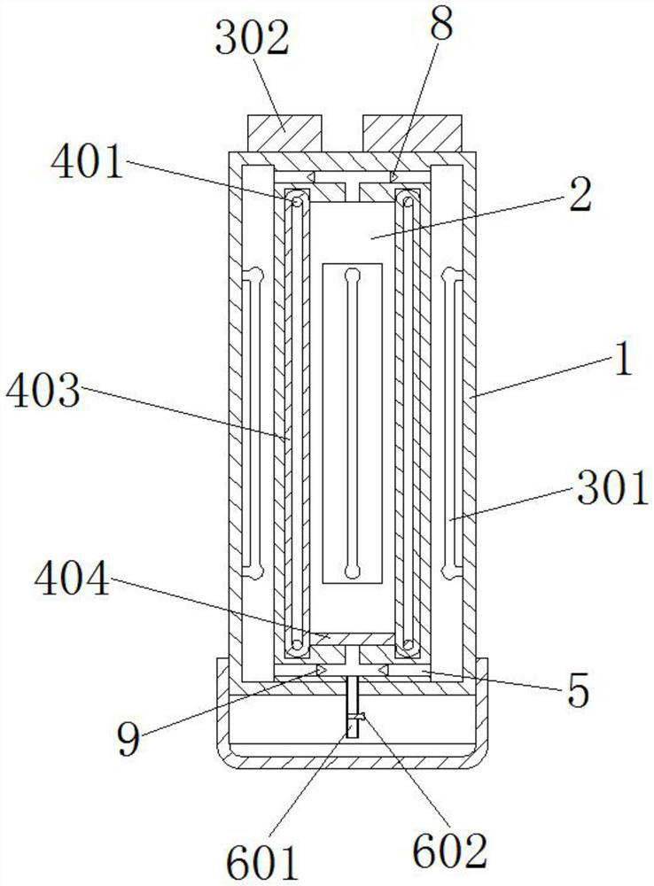
[0028] like figure 1 , figure 2 As shown in the figure, the device includes a sleeve body 1, the inner and outer sides of the sleeve body 1 are surrounded by a circle and the inner middle end is provided with a cavity 2, and a temperature control assembly 3 that can heat the contrast medium is fixed inside the cavity 2. The sleeve body 1 The drive assembly 4 connected at the inner middle end can flow the heating contrast agent. Mounting holes 5 are integrally provided on the upper and lower sides of the inner middle end of the sleeve body 1. The middle end of the sleeve body 1 is fixed through a drain. component 6;

[0029] The temperature control assembly 3 includes a heating tube 301 fixed inside the cavity 2 , the thermostat 302 fixed on the left side of the top of the casing 1 is connected to the heating tube 301 with wires, and the driving assembly 4 includes a middle end that is connected to the inner end of the casing 1 . The rotary pins 401 at the four corners, the ...

Embodiment 2

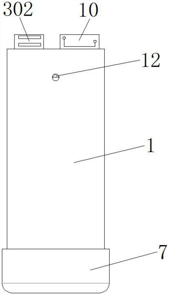
[0031] like image 3 , Figure 4 , Figure 5 As shown, the sealing cover 7 threaded on the lower end of the sleeve body 1 can isolate the catheter 601 from the outside world to ensure the cleanliness of the catheter 601 before use. The valve 8 can prevent the contrast agent from being discharged into the inner and outer cavity 2 of the sleeve 1 from the contrast agent in the inner cavity 2 of the sleeve 1 from flowing back to the cavity 2 at the inner middle of the sleeve 1 through the installation hole 5 at the upper end. Inside, the stop valves 9 fixed on the left and right sides of the mounting hole 5 at the lower end can prevent the contrast medium discharged from the inner and outer cavity 2 of the sleeve 1 into the inner cavity 2 of the sleeve 1 from passing through. The mounting hole 5 at the lower end flows back into the cavity 2 outside the casing 1. A removable lithium battery 10 is provided on the right side of the top of the casing 1. The lithium battery 10 and t...


PUM


Abstract

The invention discloses a flowing type cardiology contrast agent heating device which comprises a sleeve body, cavities are formed in the outer side of the interior of the sleeve body and the middle end of the interior of the sleeve body, a temperature control assembly capable of heating a contrast agent is fixedly connected to the interior of each cavity, and a driving assembly rotationally connected to the middle end of the interior of the sleeve body can conduct flowing treatment on the heated contrast agent. Mounting holes are integrally formed in the upper side and the lower side of the middle end in the sleeve body, and a drainage assembly fixedly penetrates through the middle end of the bottom of the sleeve body. According to the device, the contrast agent is treated in a flowing mode, the flowing contrast agent can be subjected to all-around heating treatment, the heating effect of the contrast agent is improved, and the pain of a patient when the contrast agent is injected is relieved in an auxiliary mode. According to the device, the flowing direction of the contrast agent can be controlled, the phenomenon that the contrast agent flows back in the flowing process is avoided, the stability of the flowing direction of the contrast agent in the device is ensured, and the heating effect of the device on the contrast agent is further improved.

Description

technical field [0001] The invention relates to the technical field of medical appliances, in particular to a flow-type cardiology contrast agent heating device. Background technique [0002] Contrast agents (also known as contrast agents, contrast media) are chemicals injected (or taken) into human tissues or organs to enhance image observation. The density of these articles is higher or lower than the surrounding tissue, and the resulting contrast is displayed with certain instruments. Such as X-ray observation commonly used iodine preparations, barium sulfate and so on. [0003] At present, the traditional contrast agent injection device does not have a heating function, which leads to the injection of a low-temperature contrast agent into the patient's body, which greatly increases the pain of the patient during treatment. Based on this, the present invention designs a flow type cardiology contrast agent heating device to solve the above problems. SUMMARY OF THE INVE...

Claims


Application Information

Patent Timeline
Patent Type & Authority Applications(China)
IPC IPC(8): A61M5/44A61M5/00
CPCA61M5/445A61M5/007
Inventor 刘英炜杜林翔
Owner 周口市中心医院
Why Eureka
Try Eureka