
Oil mist purification system adopting multi-stage filtering mechanism

A purification system and stage filtration technology, applied in the fields of dispersed particle filtration, chemical instruments and methods, and the use of liquid separators, etc., can solve the problems of corrosion of production equipment, single treatment method, inability to multi-stage filtration and purification treatment of oil mist, etc. High purification efficiency and the effect of avoiding the accumulation of impurities

Active Publication Date: 2022-07-22
NANTONG CHANGJIANG VALVE MFG
View PDF9 Cites 0 Cited by
  • Summary
  • Abstract
  • Description
  • Claims
  • Application Information

AI Technical Summary

Problems solved by technology

[0002] In the actual production process, the production equipment often produces a large amount of oil mist. If the oil mist is emptied directly, it will not only pose a great threat to the personal health of the operators, but also the oil mist will easily stick to the production equipment after contacting it. Connected to the surface of the production equipment, this will result in a poor sanitation environment in the entire production workshop, and it will also cause corrosion of the production equipment. Therefore, general manufacturers will perform centralized purification of the gas generated by the production equipment
[0003] At present, oil mist and fume filters are installed in the production workshop to treat the oil mist generated during the processing and production process. The oil mist exhaust gas is sucked into the oil mist filter by the induced draft fan and processed by the oil mist and fume filter. However, this treatment method is single and cannot perform multi-stage filtration and purification treatment for oil mist. Therefore, it is necessary to study an oil mist purification system with a multi-stage filtration mechanism.

Method used


Image

  • Oil mist purification system adopting multi-stage filtering mechanism
  • Oil mist purification system adopting multi-stage filtering mechanism
  • Oil mist purification system adopting multi-stage filtering mechanism

Examples


Embodiment Construction

[0026] The technical solutions in the embodiments of the present invention will be clearly and completely described below with reference to the accompanying drawings in the embodiments of the present invention. Obviously, the described embodiments are only a part of the embodiments of the present invention, but not all of the embodiments.

[0027] In the description of the present invention, it should be understood that the terms "upper", "lower", "front", "rear", "left", "right", "top", "bottom", "inside", " The orientation or positional relationship indicated by "outside" is based on the orientation or positional relationship shown in the accompanying drawings, and is only for the convenience of describing the present invention and simplifying the description, rather than indicating or implying that the indicated device or element must have a specific orientation, so as to The specific orientation configuration and operation are therefore not to be construed as limitations of...


PUM


Abstract

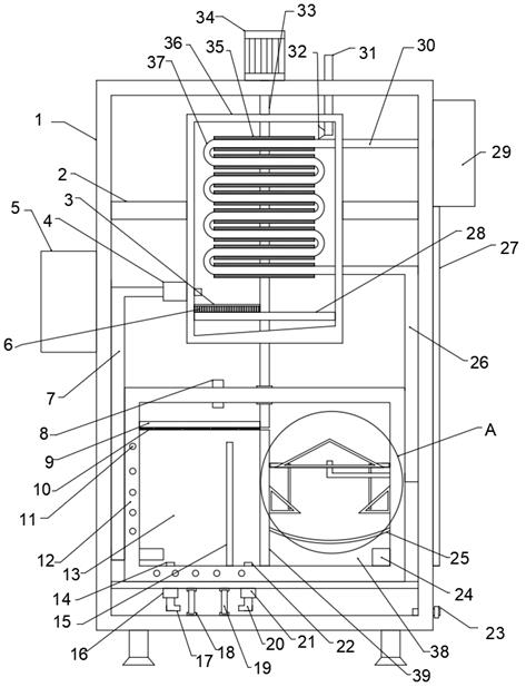
The invention belongs to the technical field of filtering, particularly relates to an oil mist purification system adopting a multi-stage filtering mechanism, and aims to solve the problems that oil mist smoke filters are installed in production workshops to treat oil mist generated in the processing and production process, however, the treatment mode is single, and the oil mist cannot be subjected to multi-stage filtering and purification treatment on a box body. According to the scheme, the device comprises a box body, an electric control mechanism is fixedly connected to the outer wall of one end of the box body, a motor is fixedly connected to the outer wall of the top of the box body, a feeding pipe is fixedly connected to the outer wall of the top of the box body, and fixing rods are fixedly connected to the two ends of the inner wall of the box body. By arranging a third filter plate, liquefied oil can be subjected to impurity filtering treatment, part of oil mist is sucked into a first gas guide pipe through an air suction pump, the oil mist is guided into the water tank through conveying of the first gas guide pipe, the oil mist is treated through an oil scraping mechanism and an oil collecting mechanism arranged in the water tank, and the oil mist can be filtered out through the oil scraping mechanism and the oil collecting mechanism. And the purpose of multi-stage filtering treatment is achieved.

Description

technical field [0001] The invention relates to the technical field of filtration, in particular to an oil mist purification system using a multi-stage filtering mechanism. Background technique [0002] In the actual production process, the production equipment often produces a large amount of oil mist. If the oil mist is directly emptied, it will not only pose a great threat to the personal health of the operator, but also easily stick to the oil mist after contacting the production equipment. It is connected to the surface of the production equipment, which will cause the sanitation environment of the entire production workshop to be poor, and will also cause the corrosion of the production equipment. Therefore, ordinary manufacturers will centrally purify the gas generated by the production equipment. [0003] At present, oil mist and fume filters are installed in the production workshop to treat the oil mist generated during the processing and production process. Then, ...

Claims


Application Information

Patent Timeline
IPC IPC(8): B01D50/00B01D50/60B01D46/10B01D46/681B01D47/02B01D53/00B01D53/14B01D17/025
CPCB01D50/00B01D46/10B01D53/002B01D47/02B01D53/1481B01D17/0208
Inventor 王世伟朱伟军
Owner NANTONG CHANGJIANG VALVE MFG
Learn More