
Hierarchical floating locking type power component punching device

A punching device and locking technology, which is applied in the field of hierarchical floating and locking power component punching devices, can solve the problems of increasing production costs, reducing work efficiency, inconvenient unfixing of power components with different thicknesses, etc., and achieves stable Lock-up avoidance, improved applicability, effect of increased applicability and automation level

Pending Publication Date: 2022-07-22
江阴市查克拉科技有限公司
View PDF8 Cites 0 Cited by
  • Summary
  • Abstract
  • Description
  • Claims
  • Application Information

AI Technical Summary

Problems solved by technology

[0003] In the process of processing power components, in order to prevent layer deviation, slippery board or to facilitate the installation and fixation of components, it is usually necessary to perform punching operations on them. However, the existing punching devices for power components mainly have the following problems: the existing punching devices do not It is convenient to punch holes for irregular power components, especially when punching Z-type power components, the corresponding mold must be prepared first, and the bending height of Z-type power components is different, resulting in high mold cost and low applicability , at the same time, the existing punching device is not convenient to realize the fixing of power components with different thicknesses during punching and the unfixing after punching, and often requires manual operation and debugging, which not only reduces work efficiency but also increases production costs

Method used


Image

  • Hierarchical floating locking type power component punching device
  • Hierarchical floating locking type power component punching device
  • Hierarchical floating locking type power component punching device

Examples


Embodiment Construction

[0032] The technical solutions in the embodiments of the present invention will be clearly and completely described below with reference to the accompanying drawings in the embodiments of the present invention. Obviously, the described embodiments are only a part of the embodiments of the present invention, rather than all the embodiments; based on the The embodiments of the present invention, and all other embodiments obtained by those of ordinary skill in the art without creative work, fall within the protection scope of the present invention.

[0033] In the description of the present invention, it should be understood that the terms "upper", "lower", "front", "rear", "left", "right", "top", "bottom", "inside", " "Outside" and other indications of orientation or positional relationship are based on the orientation or positional relationship shown in the accompanying drawings, which are only for the convenience of describing the present invention and simplifying the descripti...


PUM


Abstract

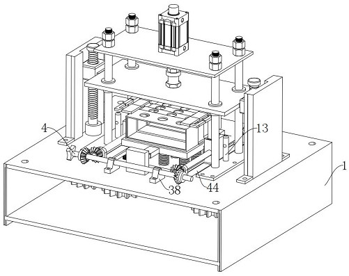
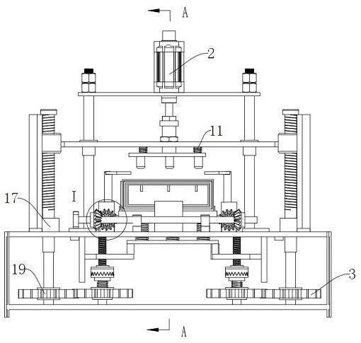
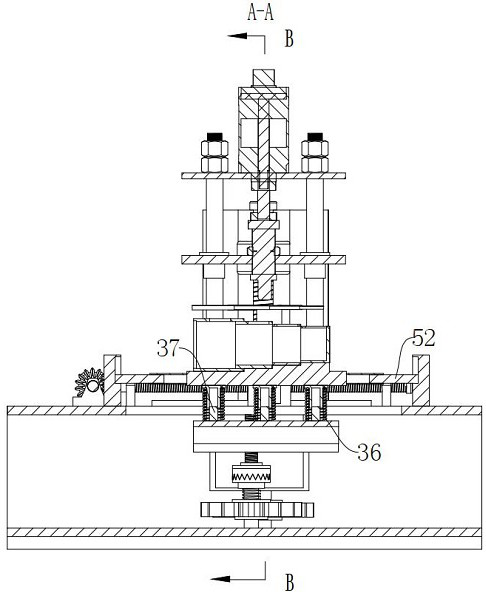
The invention discloses a hierarchical floating locking type punching device for power components. The hierarchical floating locking type punching device comprises a punching device body, a pressing punching assembly, a fastening anti-shake mechanism and a multi-dimensional adaptive adjusting assembly. The invention belongs to the technical field of electric power component punching devices, and particularly relates to a hierarchical floating locking type electric power component punching device. The punching device can adjust the adaptive placement position and the punching position according to the shapes of the power components through the arranged multi-dimensional adaptive adjusting assembly, and in order to lock the power components with different thicknesses, through the arrangement of the fastening anti-shake mechanism, the characteristics of punched holes are utilized, and the punching precision is improved. Therefore, an independent sensing mechanism and an independent locking driving mechanism do not need to be arranged, the locking process and the punching process are synchronous, the locking process and the punching finishing resetting process are synchronous, stable locking of the power component is achieved, meanwhile, the contradiction between the punching displacement difference and the thickness difference of the power component is avoided, and the punching quality of the power component is improved. And the automation level of the punching device is increased.

Description

technical field [0001] The invention belongs to the technical field of punching devices for power components, in particular to a level floating locking type punching device for power components. Background technique [0002] Power components refer to high-power electronic devices used in power conversion and control circuits of power equipment, such as circuit boards, amplifiers, radio receivers, oscillators, integrated circuits, etc. [0003] In the process of processing power components, in order to prevent layer deviation, slide plates or facilitate the installation and fixation of components, it is usually necessary to perform punching operations. However, the existing punching devices for power components mainly have the following problems: the existing punching devices do not It is convenient to punch irregular power components, especially the corresponding molds must be prepared when punching Z-type power components, and Z-type power components have different bending ...

Claims


Application Information

Patent Timeline
IPC IPC(8): B21D28/24B21D28/34B21D28/04B21D28/00B21D43/20
CPCB21D28/24B21D28/34B21D28/04B21D28/002B21D43/20
Inventor 薛颖徐沈平
Owner 江阴市查克拉科技有限公司
Learn More