
Feeding and cutting mechanism and method

A cutting and stripping technology, which is applied in the field of lithium battery automation equipment, can solve problems such as mechanical cam metal collision, pole piece pulling, mechanical shock and vibration, and achieve the effect of avoiding the risk of broken tape and avoiding mechanical shock and vibration

Pending Publication Date: 2022-07-22
SUZHOU JIERUISI INTELLIGENT TECH CO LTD
View PDF14 Cites 0 Cited by
  • Summary
  • Abstract
  • Description
  • Claims
  • Application Information

AI Technical Summary

Problems solved by technology

[0003] However, there are defects in the above chasing cutting structure and chasing cutting method, for example: the mechanical cam will produce metal collisions, resulting in mechanical shock and vibration; the mechanical cam is a processed part, and the machining accuracy may have deviations, resulting in insufficient timing for fixing the pole pieces of the film feeding assembly Accurate, the cutter assembly fails to cut off the pole piece in time after the film feeding assembly fixes the pole piece, because the winding speed of the needle will fluctuate, during this period the needle and the film feeding assembly will pull the pole piece, resulting in extreme There is a risk of breaking the tape

Method used


Image

  • Feeding and cutting mechanism and method
  • Feeding and cutting mechanism and method
  • Feeding and cutting mechanism and method

Examples


Embodiment Construction

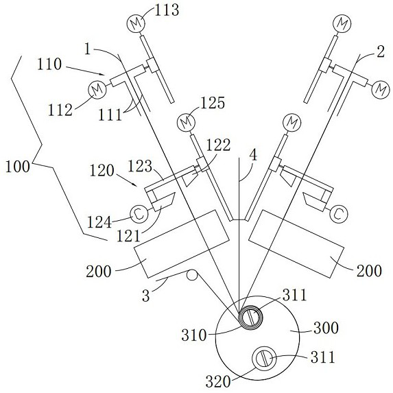
[0027] The present invention will be further described below with reference to the accompanying drawings and specific embodiments, so that those skilled in the art can better understand the present invention and implement it, but the embodiments are not intended to limit the present invention.

[0028] This embodiment is described by taking the feeding and cutting of the pole piece material tape as an example, and other embodiments can also be set as the feeding and cutting operation of other tapes. figure 1 As shown in , the cutting direction of the pole piece web is perpendicular to the conveying direction of the pole piece web.

[0029] like figure 1 As shown, the feeding cutting mechanism 100 in this embodiment includes a sheet feeding assembly 110 and a cutting knife assembly 120 . A pre-rolling mechanism 200 is provided downstream of the feeding cutting mechanism 100 along the conveying direction of the pole piece material belt. The pre-rolling mechanism 200 is used for...


PUM


Abstract

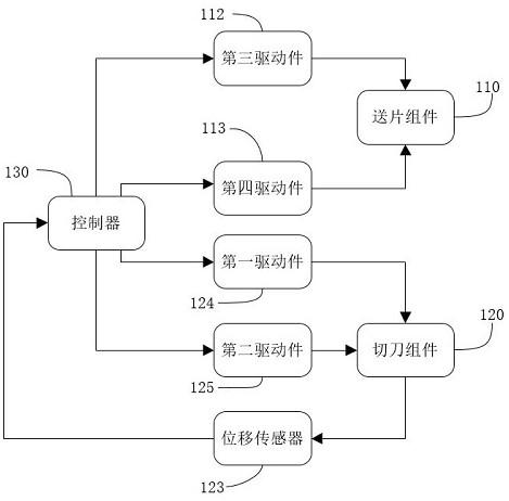
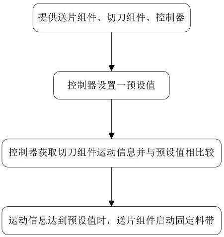
The invention discloses a feeding and cutting mechanism and method. The feeding and cutting mechanism comprises a sheet feeding assembly driven to fix a material belt, a cutter assembly driven to cut off the material belt and a controller for controlling the sheet feeding assembly. The controller controls the sheet feeding assembly to fix the material belt according to the movement time or the movement position of the cutter assembly. The opportunity of fixing the pole piece material belt by the piece feeding assembly is controlled according to the movement time or the movement position of the cutter assembly, the displacement sensor is arranged to detect the movement information of the movable cutter in the cutting direction, when the movement information reaches a preset value, the piece feeding assembly is controlled to fix the pole piece material belt, a clear starting signal is provided, and the cutter assembly is started to work. After the pole piece feeding assembly fixes the pole piece material belt, the cutter assembly cuts off the pole piece material belt in time, and the risk of belt breakage is avoided; and the movement of the sheet feeding assembly and the cutter assembly in the cutting direction is directly driven by the driving piece instead of a mechanical cam, so that mechanical impact and vibration are avoided.

Description

technical field [0001] The invention belongs to the field of lithium battery automation equipment, and in particular relates to a feeding and cutting mechanism and method. Background technique [0002] In the production process of lithium batteries, the free end of the pole piece material is fed to the winding needle. After the winding needle is wound for a certain period of time, the pole piece material needs to be cut off at the set position, and the tail of the front pole piece material after cutting. It is continued to be wound and glued to form a battery core, and the free end of the rear pole piece material tape needs to be fixed. In the prior art, in order to ensure the winding efficiency and cutting accuracy of the pole piece material tape, the method of chase cutting is usually adopted. Down, through the mechanical cam to control the cutter assembly to cut the pole piece before the pole piece is fixed to the pole piece. [0003] However, the above-mentioned chase-...

Claims


Application Information

Patent Timeline
Patent Type & Authority Applications(China)
IPC IPC(8): B23D25/02B21D43/04B23Q17/00
CPCB23D25/02B21D43/04B23Q17/00
Inventor 邱毅叶宗锋张永胜
Owner SUZHOU JIERUISI INTELLIGENT TECH CO LTD
Learn More