Railway line component laying and replacing operation method
A technology for line components and railways, which is applied in the field of laying and hoisting railway line components, can solve the problems of difficulty in adapting to operation requirements, operation safety risks, occupation of adjacent line space, etc., and achieves light weight, high integration and intelligence. The effect of improving work efficiency
- Summary
- Abstract
- Description
- Claims
- Application Information
AI Technical Summary
Problems solved by technology
Method used
Image
Examples
Embodiment 1
[0063] as attached Figure 11 As shown, an embodiment of a method for laying and replacing railway line components of the present invention specifically includes the following steps:
[0064] S101) The door hanger 100 retracts the left and right legs, and is fixed on the first flat car 300 and transported to the work site, as shown in the attached Figure 12 shown;
[0065] S102) After arriving at the construction site, deploy the door hanging device 100 through the lifting platform 200, the left and right outriggers of the door hanging device 100 are extended and supported to the working surface 900 (ie the roadbed), and the level of the truss 4 is adjusted. A flat cart 300 withdraw, as attached Figure 13 shown;
[0066] S103) The door hoisting device 100 hoists the new line component 500 placed on the second flat car 400 and transported below it, and the second flat car 400 is withdrawn, as shown in the appendix Figure 14 shown;
[0067] S104) The door hanging device ...
Embodiment 2
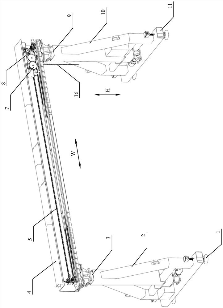
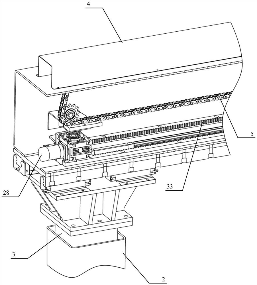
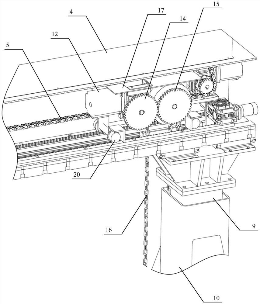
[0085] as attached figure 1 As shown, an embodiment of the door hanger 100 applied to the operation method for laying and replacing railway line components of the present invention described in Embodiment 1 specifically includes:
[0086] truss 4;
[0087] It is arranged on the truss 4 and can be carried out laterally along the truss 4 (as attached figure 1 The traverse travel mechanism 8 that moves in the direction shown in W) to adjust the hoisting position; the traverse travel mechanism 8 includes a lifting mechanism 7, and the lifting mechanism 7 can drive the chain 16 to lift and move vertically, and the end of the chain 16 is set There is a hook 6, and the hook 6 is further connected with a spreader 700, and is clamped by the spreader 700 to realize the transportation of railway line components;
[0088]The left and right legs are respectively movably arranged on the lower parts of the left and right ends of the truss 4 , and the left and right legs can move laterally ...
Embodiment 3
[0099] as attached Figure 10 As shown, it is a schematic diagram of the transportation structure of the door hanging device 100 on the rail flat car described in Embodiment 2. The door hanging device 100 and the lifting platform 200 are both arranged on the first flat car 300, and the door hanging device 100 is further fixed on the lifting platform. 200, the lifting platform 200 has lifting and rotating functions. A new line component 500 for replacement is placed on the second flat car 400 . The door hanger 100 placed on the first flat car 300 and the new line component 500 placed on the second flat car 400 are transported to the construction area by the rail car 1000 powered. After arriving at the designated construction area, the door hanging device 100 places the outriggers on both lateral sides of the door hanging device 100 with the specified designation of the roadbed 900 on both sides of the basic rail 800 of the line through the lifting and rotating actions of the l...
PUM
 Abstract
Description
Claims
Application Information
 - R&D
- Intellectual Property
- Life Sciences
- Materials
- Tech Scout
- Unparalleled Data Quality
- Higher Quality Content
- 60% Fewer Hallucinations
Browse by: Latest US Patents, China's latest patents, Technical Efficacy Thesaurus, Application Domain, Technology Topic, Popular Technical Reports.
© 2025 PatSnap. All rights reserved.Legal|Privacy policy|Modern Slavery Act Transparency Statement|Sitemap|About US| Contact US: help@patsnap.com


