Corrugated turbulent flow plane cooling device and application

A cooling device and corrugated technology, applied in jet propulsion devices, machines/engines, etc., can solve the problems of engine thrust loss, waste of cold air, etc., and achieve the effect of less cooling air, high cooling efficiency, and reduced thrust loss.

Inactive Publication Date: 2022-07-22
NORTHWESTERN POLYTECHNICAL UNIV
View PDF0 Cites 1 Cited by
  • Summary
  • Abstract
  • Description
  • Claims
  • Application Information

AI Technical Summary

Problems solved by technology

On the other hand, excessive use of cold air to cool the wall will form a thicker air film boundary layer on the wall, which will cause loss of engine thrust
In addition, due to the low-pressure suction of gas in the expansion section, most of the cooling air is drawn to the expansion section with milder working conditions, which to some extent causes waste of cooling air

Method used


Image

  • Corrugated turbulent flow plane cooling device and application
  • Corrugated turbulent flow plane cooling device and application
  • Corrugated turbulent flow plane cooling device and application

Examples


Embodiment Construction

[0032] The embodiments described below with reference to the accompanying drawings are exemplary, and are intended to explain the present invention and should not be construed as limiting the present invention.

[0033] In the description of the present invention, it should be understood that the terms "center", "longitudinal", "lateral", "length", "width", "thickness", "upper", "lower", "front", " rear, left, right, vertical, horizontal, top, bottom, inside, outside, clockwise, counterclockwise, etc., or The positional relationship is based on the orientation or positional relationship shown in the accompanying drawings, which is only for the convenience of describing the present invention and simplifying the description, rather than indicating or implying that the referred device or element must have a specific orientation, be constructed and operated in a specific orientation, Therefore, it should not be construed as a limitation of the present invention.

[0034] This exa...


PUM


Abstract

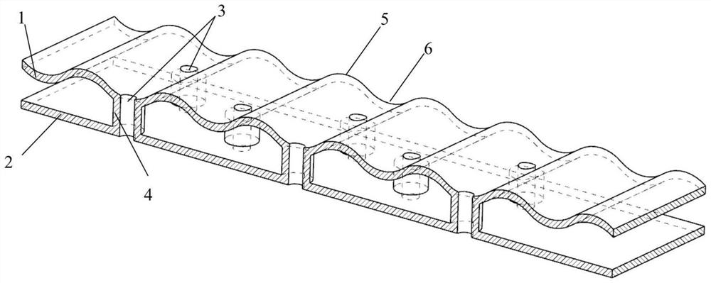
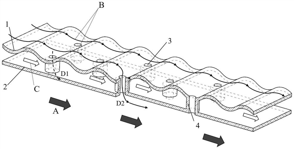
The invention discloses a corrugated turbulent flow plane cooling device and application, and belongs to the field of aero-engines. Comprising a cold side corrugated plate, a hot side flat plate and hollow turbulent flow columns, the cold side corrugated plate is located on one side of a cold air channel, and the hot side flat plate is located on one side of a high-temperature fuel gas channel; a hill-shaped middle channel with the sectional area changing periodically is formed between the cold side corrugated plate and the hot side flat plate. A plurality of hollow turbulent flow columns are arranged between the cold side corrugated plate and the hot side flat plate to form a middle channel containing the hollow turbulent flow columns, and the cold air channel is communicated with the high-temperature fuel gas channel through hollow holes in the hollow turbulent flow columns; the hollow turbulent flow columns are connected with wave troughs of the hot side flat plate and the cold side corrugated plate; and a gas film protection layer is formed on the hot-side flat plate by utilizing outflow of a trough high-pressure area of the cold-side corrugated plate. According to the invention, the amount of cold air near the wall surface of the spray pipe is reduced, and the thrust loss of the engine caused by cold air mixing is reduced under the condition of achieving higher cooling efficiency.

Description

technical field [0001] The invention belongs to the field of aero-engines, and in particular relates to a corrugated spoiler plane cooling device and its application. Background technique [0002] When military fighters take off at short distances and maneuver quickly, they often obtain additional thrust through afterburner beyond the maximum throttle opening of the engine. Due to the limited space in the afterburner, the still-burning gas acts on the nozzle wall of the converging section of the engine in the form of oblique impact, which is likely to cause gas backflow and cause serious consequences. Studies have shown that the gas temperature of the tail nozzle will be as high as 2000K at this time. In addition, the pressure gradient from the inlet to the outlet of the engine nozzle is relatively large, which is likely to cause a strong suction of the gas in the expansion section, which aggravates the occurrence of the backflow phenomenon in the convergent section. [00...

Claims


Application Information

Patent Timeline
Patent Type & Authority Applications(China)
IPC IPC(8): F02K1/82
CPCF02K1/822Y02T50/60
Inventor 朱惠人徐志鹏李晋礴张丽郭涛
Owner NORTHWESTERN POLYTECHNICAL UNIV
Why Eureka
Try Eureka