
Hole wall coupling device of stress-strain sensor

A sensor hole, stress and strain technology, applied in the direction of measuring devices, instruments, measuring force, etc., can solve the problems of non-circular aperture, sensor coupling, falling blocks, etc., and achieve the effect of improving accuracy and ensuring normal contact

Active Publication Date: 2022-07-22
INST OF GEOMECHANICS
View PDF15 Cites 0 Cited by
  • Summary
  • Abstract
  • Description
  • Claims
  • Application Information

AI Technical Summary

Problems solved by technology

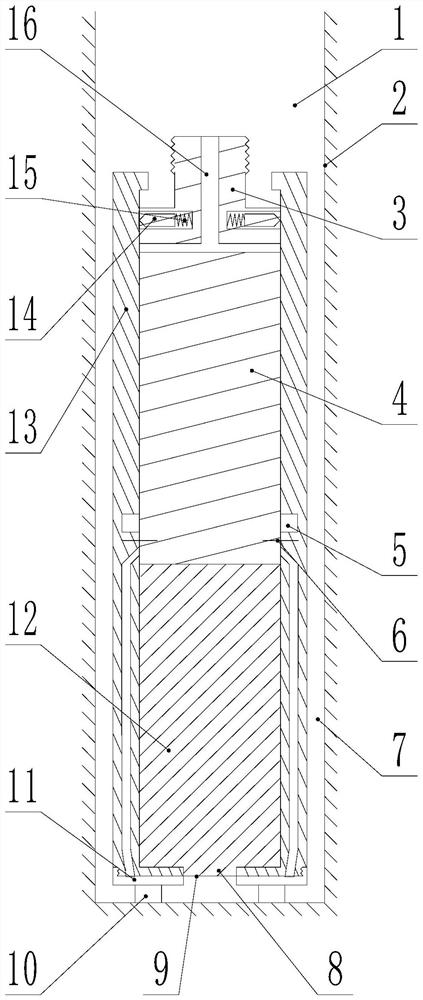
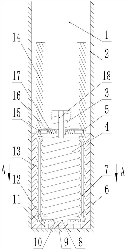
[0009] However, when the hole diameter is non-circular due to various objective factors such as drilling level, or the rock mass at the observation point is incomplete so that the hole wall has cracks or even blocks, the sensor of the measuring element cannot be in contact with the hole wall. normal contact, this method will face a serious problem of coupling the sensor to the borehole wall

Method used


Image

  • Hole wall coupling device of stress-strain sensor
  • Hole wall coupling device of stress-strain sensor
  • Hole wall coupling device of stress-strain sensor

Examples


Embodiment Construction

[0036] In order to make the purposes, technical solutions and advantages of the embodiments of the present invention clearer, the technical solutions in the embodiments of the present invention will be clearly and completely described below with reference to the accompanying drawings in the embodiments of the present invention. Obviously, the described embodiments These are some embodiments of the present invention, but not all embodiments. The components of the embodiments of the invention generally described and illustrated in the drawings herein may be arranged and designed in a variety of different configurations.

[0037] Thus, the following detailed description of the embodiments of the invention provided in the accompanying drawings are not intended to limit the scope of the invention as claimed, but are merely representative of selected embodiments of the invention. Based on the embodiments of the present invention, all other embodiments obtained by those of ordinary s...


PUM


Abstract

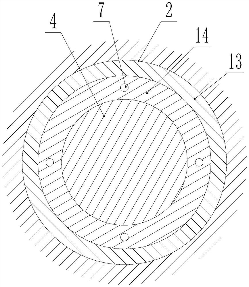
The invention relates to the technical field of ground stress monitoring, in particular to a stress-strain sensor hole wall coupling device. The hole wall coupling device of the stress-strain sensor comprises a base, a shell, a piston, a filler and a sealing film, the base is arranged at one end of the shell; the shell is cylindrical, the piston and the filler are arranged in the shell, and a connector is arranged at the end, away from the filler, of the piston; a first discharge port is formed in the end, close to the base, of the shell, and the sealing film is arranged at the first discharge port and used for blocking the first discharge port. The embodiment of the invention has the beneficial effects that the filler is extruded by the piston to be discharged from the first discharge port of the shell and then distributed between the shell and the hole wall, and a perfect circular drill hole can be obtained after the filler is filled and solidified, so that the coupling of the sensor and the hole wall can be ensured, and the normal contact of the sensor and the hole wall is further ensured; and the accuracy of ground stress monitoring is improved.

Description

technical field [0001] The invention relates to the technical field of in-situ stress monitoring, in particular to a hole-wall coupling device of a stress-strain sensor. Background technique [0002] In-situ stress is a kind of natural force that objectively exists in the crustal rock body and is not disturbed by engineering. In-situ stress monitoring is to understand the change of the stress value in the crust with time, and it is a real-time dynamic stress measurement. It is necessary for earthquake prediction and research to carry out continuous dynamic monitoring of stress and strain in the shallow and even deep parts of the crust. [0003] The basic principle of the in-situ stress monitoring method is to install the measuring probe in the borehole of the crustal rock mass, and the borehole is deformed by tectonic stress in the crustal rock mass to generate micro-strain, and the measuring element is well coupled with the borehole rock wall. By recording the continuous ...

Claims


Application Information

Patent Timeline
Patent Type & Authority Applications(China)
IPC IPC(8): G01L1/00G01B21/32
CPCG01L1/00G01B21/32
Inventor 张士安吴满路张重远
Owner INST OF GEOMECHANICS
Learn More