
Strain foot structure and torque measuring platform

A torque measurement and platform technology, applied in the field of torque measurement platform and strain foot structure, can solve the problems of inter-dimensional coupling error, poor dynamic characteristics of piezoelectric ceramics, and reduce platform stiffness, achieve good low-frequency dynamic characteristics, and reduce inter-dimensional The effect of coupling and improving the load capacity

Pending Publication Date: 2022-07-22
CHANGCHUN INST OF OPTICS FINE MECHANICS & PHYSICS CHINESE ACAD OF SCI
View PDF0 Cites 1 Cited by
  • Summary
  • Abstract
  • Description
  • Claims
  • Application Information

AI Technical Summary

Problems solved by technology

[0003] At present, the ground measurement of the vibration source mostly uses piezoelectric structures to test the disturbance force, among which the Stewart configuration is the most commonly used, but its loose structure will significantly reduce the stiffness of the platform. In addition, the dynamic characteristics of piezoelectric ceramics at low frequencies are very Not good, it is difficult to have a good measurement of low-frequency vibration, and the Stewart configuration has coupling to the torque, which needs to be decoupled during the measurement process, which will inevitably introduce inter-dimensional coupling errors

Method used


Image

  • Strain foot structure and torque measuring platform
  • Strain foot structure and torque measuring platform
  • Strain foot structure and torque measuring platform

Examples


Embodiment Construction

[0093] In order to make the objectives, technical solutions and advantages of the present invention clearer, the present invention will be further described in detail below with reference to the accompanying drawings and specific embodiments. It should be understood that the specific embodiments described herein are only used to explain the present invention, but not to limit the present invention.

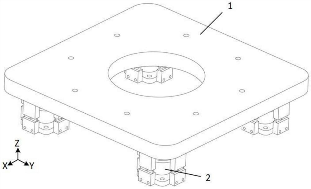
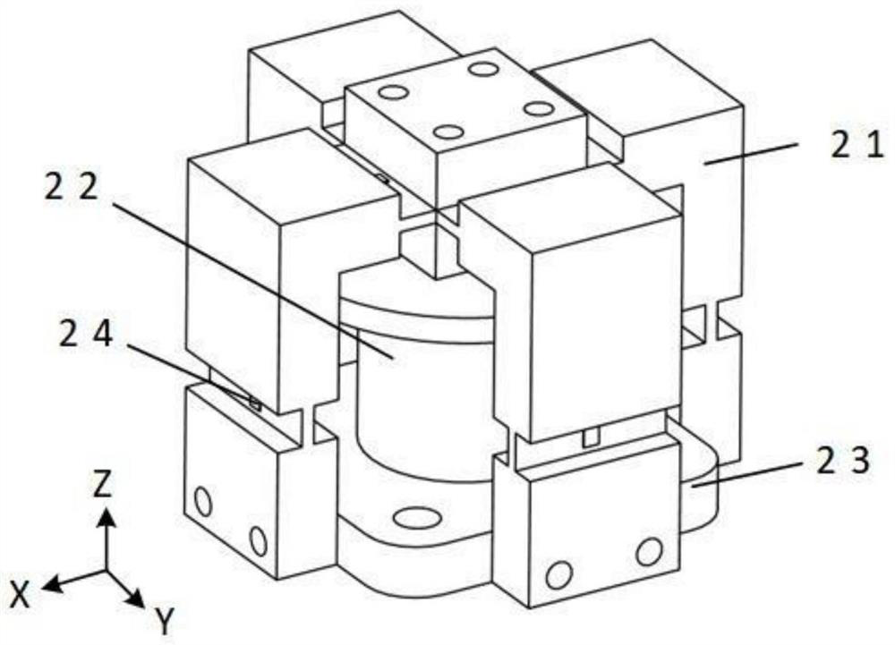
[0094] like figure 2 , Figure 5 and Image 6 As shown, in the first aspect, the present invention provides a strain foot structure 2 including a loading block 211 , a connecting block, a fixing block and a base 23 .

[0095] The top surface of the loading block 211 is provided with at least one first positioning hole 2118;

[0096] The shape of the connecting block is L-shaped, including a horizontal connecting part and a vertical connecting part, the horizontal connecting part and the vertical connecting part are arranged vertically, and the horizontal connecting part is con...


PUM


Abstract

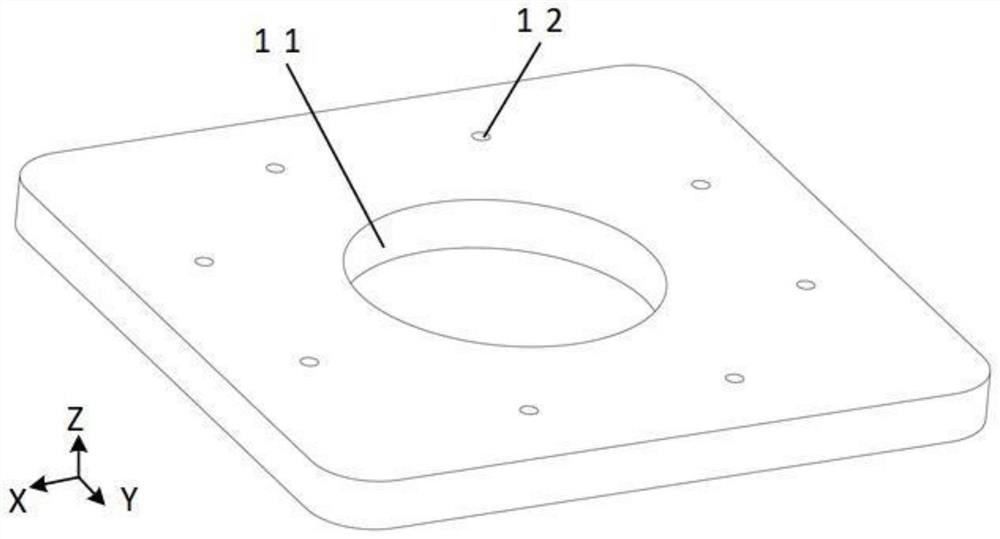
The invention discloses a strain foot structure and a moment measurement platform, the moment measurement platform comprises a plurality of strain foot structures and a placement table, the placement table is supported by the plurality of strain foot structures, and the load capacity of the placement table is improved. Each strain foot structure comprises a loading block, a connecting block and a fixing block; the connecting block comprises a horizontal connecting part and a vertical connecting part, the horizontal connecting part and the vertical connecting part are vertically arranged, and the horizontal connecting part is connected with one side of the loading block through the horizontal strain beam; and the fixed block is arranged below the vertical connecting part and is connected with the bottom surface of the vertical connecting part through the vertical strain beam. Through the horizontal strain beam and the vertical strain beam arranged in the strain foot structure, the inter-dimensional coupling is reduced, the measurement precision of the torque measurement platform is improved, and the strain gauges are respectively arranged on the horizontal strain beam and the vertical strain beam, so that the torque measurement platform has a relatively good low-frequency dynamic characteristic.

Description

technical field [0001] The invention relates to the field of micro-vibration measurement, in particular to a strain foot structure and a moment measurement platform. Background technique [0002] With the continuous development of space telescope technology, the requirements for its pointing stability are higher, and the indicators for micro-vibration are also more stringent. In order to explore the influence of micro-vibration on large-scale equipment such as telescope systems, it is particularly important to study the vibration disturbance characteristics of the vibration source. The mass of the space telescope plus its tooling can reach more than one ton, so a moment measurement platform is needed, which can meet the requirements of measuring the vibration source of large aerospace equipment in terms of accuracy, size and load capacity. [0003] At present, the ground measurement of the vibration source mostly uses piezoelectric structures to test the disturbance force. ...

Claims


Application Information

Patent Timeline
IPC IPC(8): G01M7/02G01L5/16
CPCG01M7/025G01L5/16
Inventor 夏明一徐振邦周成波朱文博
Owner CHANGCHUN INST OF OPTICS FINE MECHANICS & PHYSICS CHINESE ACAD OF SCI
Learn More