
Variable-angle fixing test system for test piece in airplane discrete source impact damage test

A technology of impact damage and fixed testing, which is applied in impact testing, material strength testing using one impact force, and aircraft component testing. Stepless adjustment, the effect of improving accuracy

Active Publication Date: 2022-07-22
CHINA AIRPLANT STRENGTH RES INST
View PDF17 Cites 0 Cited by
  • Summary
  • Abstract
  • Description
  • Claims
  • Application Information

AI Technical Summary

Problems solved by technology

[0003]At present, in the direction of structural anti-discrete source impact, numerical analysis methods are mainly used for variable-angle impact research, and the test is only carried out for small plate structures.
In addition, the variable-angle test platforms currently used are relatively bulky, or a set of special fixture devices are processed for the angles that need to be studied; or they are built with simple structures, which cannot be used stably, reliably and for a long time

Method used


Image

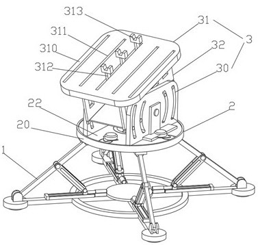
  • Variable-angle fixing test system for test piece in airplane discrete source impact damage test
  • Variable-angle fixing test system for test piece in airplane discrete source impact damage test
  • Variable-angle fixing test system for test piece in airplane discrete source impact damage test

Examples


Embodiment 1

[0046] like figure 1 The shown test system for variable angle fixing of the test piece in the aircraft discrete source impact damage test includes a support device 1 arranged horizontally on the ground, and a variable angle fixing test bench arranged on the support device 1;

[0047] The variable-angle fixed test stand includes a first angle adjustment device 2 arranged on the support device 1, and a second angle adjustment device 3 movably arranged on the first angle adjustment device 2;

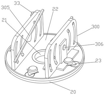
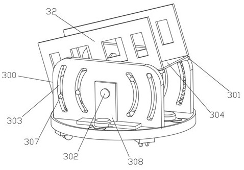
[0048] like figure 2 As shown, the first angle adjusting device 2 includes a circular connecting plate 20 fixedly arranged above the supporting device 1, an annular bushing 21 arranged in the center of the circular connecting plate 20, and movably arranged on the annular connecting plate 20. a rotating disk 22 on the shaft sleeve 21 and having the same diameter as the circular connecting disk 20, and a power assembly 23 arranged between the circular connecting disk 20 and the rotating dis...

Embodiment 2

[0059] The difference from Example 1 is:

[0060] like Figure 5 As shown, the support device 1 includes a bottom base plate 10 arranged on a level ground, an attitude adjustment assembly arranged on the bottom base plate 10 and connected with a circular connecting plate 20;

[0061] The bottom base plate 10 includes a central fixed plate 100 horizontally arranged on the ground, four extension rods 101 arranged on the central fixed plate 100 and evenly distributed along the radial direction of the central fixed plate 100, and a plurality of extension rods 101 are respectively arranged on the central fixed plate 100. the connecting seat 102 at the end of the extension rod 101;

[0062] The upper surface of the connection seat 102 is provided with a first connection lifting lug 103, and the lower surface of the connection seat 102 is provided with a grounding fixing component 106;

[0063] Four second connecting lugs 104 corresponding to the first connecting lugs 103 are movab...

Embodiment 3

[0070] The difference from Example 2 is:

[0071] like Figure 7 As shown, the adjusting rod 113 includes an I-shaped adjusting rod 114 whose upper end is hinged with the support rod 110, and a U-shaped sliding rod 115, which is slidably arranged on the I-shaped adjusting rod 114 and whose lower end is hinged with the hydraulic push cylinder 112;

[0072] The I-shaped adjusting rod 114 is provided with a locking rack; the U-shaped sliding rod 115 is provided with a ratchet device 116 connected with the locking rack.

[0073] A hinged connection piece 117 is provided at the connection between the hydraulic push cylinder 112 and the U-shaped sliding rod 115;

[0074] The upper surface of the extension rod 101 is provided with a limiting groove 118;

[0075] The hinged connection member 117 is slidably disposed on the limiting groove 118 .


PUM


Abstract

The invention relates to the technical field of aircraft testing, and discloses a variable-angle fixing test system for a test piece in an aircraft discrete source impact damage test, which comprises a supporting device horizontally arranged on the ground and a variable-angle fixing test bed arranged on the supporting device, the variable-angle fixed test bench comprises a first angle adjusting device arranged on the supporting device and a second angle adjusting device movably arranged on the first angle adjusting device; the first angle adjusting device comprises a circular connecting disc fixedly arranged above the supporting device, an annular shaft sleeve arranged in the center of the circular connecting disc, a rotating disc movably arranged on the annular shaft sleeve, and a power assembly arranged between the circular connecting disc and the rotating disc, wherein the diameter of the rotating disc is consistent with that of the circular connecting disc. According to the invention, different postures of the test piece can be controlled, and the accuracy of the impact damage test result of the discrete source is effectively improved.

Description

technical field [0001] The invention relates to the technical field of aircraft testing, in particular to a variable-angle fixing test system for a test piece in an aircraft discrete source impact damage test. Background technique [0002] For high-speed vehicles such as airplanes and high-speed rails, during high-speed operation, they may face contact and impact damage from external discrete sources such as hail, birds, and runway debris; airplane noses, wing skins, engine blades, cars or high-speed rails The windshield and so on are all of streamlined design, and the surface is a complex shape optimized for aerodynamics and strength. Uncontrollable damage will occur when facing the impact damage of discrete sources; therefore, when evaluating the aircraft nose In the experiment of the impact resistance of structures such as wing skins, the real boundary environment must be simulated as much as possible, and the influence of the impact angle of the discrete source must be c...

Claims


Application Information

Patent Timeline
Patent Type & Authority Applications(China)
IPC IPC(8): G01M7/08B64F5/60G01N3/02G01N3/30B25H1/02B25H1/08B25H1/18
CPCG01M7/08G01N3/02G01N3/30B64F5/60B25H1/02B25H1/08B25H1/18
Inventor 张宇王彬文白春玉王计真
Owner CHINA AIRPLANT STRENGTH RES INST
Learn More