Virtual impedance design method for grid-following type inverter based on parameter stability boundary

A technology of stabilizing boundary and virtual impedance, applied in the field of power electronics, can solve the problem that the grid-connected inverter cannot be synchronized with the grid-type inverter, the island micro-grid system cannot maintain stable operation, and the lack of large grid frequency and voltage support, etc. It can achieve the effect of simple and clear calculation results, avoiding the lack of damping and instability, and improving the damping of the power grid system.

Pending Publication Date: 2022-07-22
PANZHIHUA POWER SUPPLY COMPANY STATE GRID SICHUAN ELECTRIC POWER +2
View PDF0 Cites 0 Cited by
  • Summary
  • Abstract
  • Description
  • Claims
  • Application Information

AI Technical Summary

Problems solved by technology

[0003] Most new energy grid-connected inverters are grid-connected inverters, whose external characteristics are current sources. By directly controlling the output current, the efficient utilization of distributed power sources is realized, but they lack frequency and voltage support capabilities.
However, in the 100% new energy island microgrid system dominated by power electronic converters, due to its own low inertia, weak damping characteristics and lack of stable frequency and voltage support of the large power grid, when the system parameters are not set properly, it may As a result, the phase-locked loop of the grid-following inverter loses stability due to lack of damping, making the grid-following inverter unable to keep pace with the grid-constructed inverter, and finally the island microgrid system cannot maintain stable operation

Method used


Image

  • Virtual impedance design method for grid-following type inverter based on parameter stability boundary
  • Virtual impedance design method for grid-following type inverter based on parameter stability boundary
  • Virtual impedance design method for grid-following type inverter based on parameter stability boundary

Examples


Embodiment Construction

[0027] Example embodiments will now be described more fully with reference to the accompanying drawings. Exemplary embodiments, however, can be embodied in various forms and should not be construed as limited to the embodiments set forth herein; rather, these embodiments are provided so that this disclosure will be thorough and complete, and will fully convey the concept of exemplary embodiments conveyed to those skilled in the art. In the drawings, the size of most elements may be exaggerated or deformed for clarity. The same reference numerals in the drawings denote the same or similar structures, and thus their detailed descriptions will be omitted.

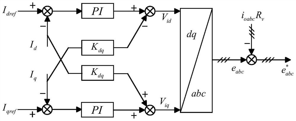
[0028] In order to effectively avoid the situation that the grid-following inverter is unstable due to lack of damping due to improper parameter setting of the grid system, the invention introduces a virtual impedance R into the grid-following inverter. v , to change the output of the grid-following inverter; the impedance R...


PUM


Abstract

The invention discloses a parameter stability boundary-based grid-following inverter virtual impedance design method, which comprises the following steps of: 1, analyzing system parameters of a power grid system formed by a grid-following inverter to obtain initial values, actual values and stability boundary values of the system parameters which influence the stability of the power grid system; and step 2, calculating virtual impedance Rv introduced into the following grid type inverter according to the initial value, the actual value and the stable boundary value of each system parameter. According to the method disclosed by the invention, the impedance value of the accessed impedance is quantitatively calculated based on the parameter stability boundary, and the calculation steps are simpler and more convenient; the impedance value of the impedance is determined by using the system equivalent resistance of the stability boundary and the instability boundary of the system parameters, and the system parameters which have great influence on the stability of the system are selected as the basis for calculating the impedance value, so that the required impedance value can be quantitatively calculated, and the result is more accurate.

Description

technical field [0001] The invention belongs to the technical field of power electronics, and in particular relates to a virtual impedance design method of a grid-following inverter based on a parameter stability boundary. Background technique [0002] With the rapid development of renewable energy sources such as wind power and photovoltaics, the penetration rate of power electronic converters as an important interface for new energy grid connection in the power system continues to increase, and the development of modern power systems is gradually showing a "double high" trend. . [0003] Most of the new energy grid-connected inverters are grid-following inverters, and their external characteristics are current sources. By directly controlling the output current, efficient utilization of distributed power sources is achieved, but they lack frequency and voltage support capabilities. In the 100% new energy island microgrid system dominated by power electronic converters, du...

Claims


Application Information

Patent Timeline
IPC IPC(8): H02J3/38H02J3/24G06F30/20G06F113/04
CPCH02J3/381H02J3/24G06F30/20H02J2203/20H02J2300/24H02J2300/28G06F2113/04
Inventor 甘德刚苟家波胡宇飞李胜戴炜杨勇波田震查晓明
Owner PANZHIHUA POWER SUPPLY COMPANY STATE GRID SICHUAN ELECTRIC POWER
Why Eureka
Try Eureka