Supercharge Your Innovation With Domain-Expert AI Agents!

Tool for installing rotor with permanent magnet into stator

A technology of rotor loading and permanent magnets, applied in the direction of centering/balancing rotors, etc., can solve the problems of low efficiency, complicated handling and assembly by operators, etc.

Active Publication Date: 2022-07-22
JIANGSU DAZHONG ELECTRIC MOTOR
View PDF6 Cites 0 Cited by
  • Summary
  • Abstract
  • Description
  • Claims
  • Application Information

AI Technical Summary

Problems solved by technology

[0003] When the rotor is installed in the casing with the stator, it is generally by manual means that the central axis of the rotor is inserted into one end of the casing, and then the rotor is rotated and installed in the stator in the casing. However, due to It is operated manually, and the rotor and the casing with the stator assembled have a certain weight. Therefore, the efficiency of assembling the rotor to the stator is low, and the reciprocating handling and assembly of the operator is more cumbersome

Method used


Image

  • Tool for installing rotor with permanent magnet into stator
  • Tool for installing rotor with permanent magnet into stator
  • Tool for installing rotor with permanent magnet into stator

Examples


Embodiment 1

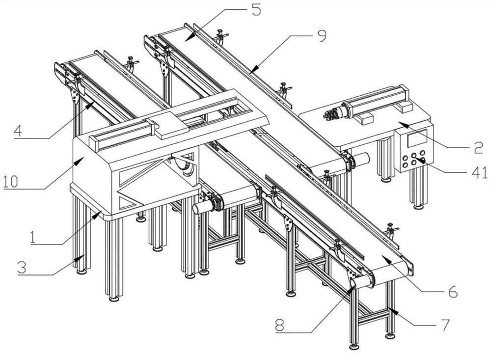
[0028] like Figure 1-Figure 5 As shown, the present invention provides a tool for installing a rotor with a permanent magnet into a stator, including a first operating table 1 and a second operating table 2, and the first operating table 1 and the four parts of the bottom are provided with first support columns 3 , a controller 41 is provided on one side of the front end of the second operating table 2, a casing conveyor belt 4 is provided on one side of the first operating table 1, and a rotor conveyor belt is provided on the side of the second operating table 2 close to the casing conveyor belt 4 5. There is a finished conveyor belt 6 between the casing conveyor belt 4 and the rotor conveyor belt 5. The casing conveyor belt 4, the rotor conveyor belt 5 and the finished product conveyor belt 6 are all provided with a second support column 7 at the bottom. The casing conveyor belt 4. The rotor conveyor belt 5 and the finished product conveyor belt 6 are provided with a first ...

Embodiment 2

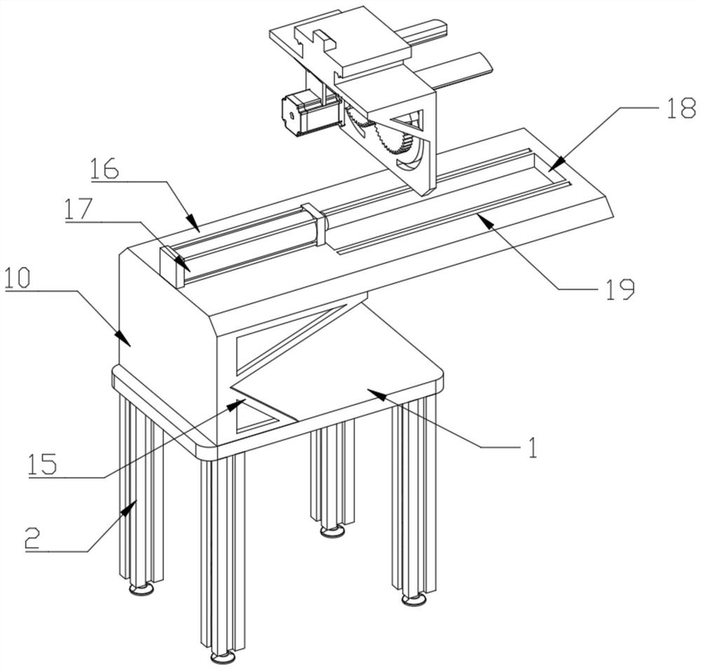
[0030]One side of the first top plate 16 is fixedly installed on the side of the first side plate 10 by welding, and a first side plate 10 is fixedly installed between the first console 1 and the walls of the first top plate 16 . The support plate 15, the first cylinder 17 is fixedly installed on the top side of the first top plate 16, and the first cylinder 17 is connected with the external gas station, and the first top plate 16 is provided with a sliding block in the wall body close to the first cylinder 17 side. 18, the top of the first top plate 16 is provided with a chute 19 at the front and rear ends of the sliding port 18, a second top plate 20 is fixedly installed above one side of the second side plate 11, and one side of the second side plate 11 is connected to the second top plate. 20. A second support plate 21 is symmetrically and fixedly installed on one side of the bottom of the second top plate 20. A T-shaped slider 22 is fixedly installed at the center of the t...


PUM


Abstract

The tool comprises a first operation table and a second operation table, first supporting columns are arranged on the periphery of the first operation table and the periphery of the bottom of the first operation table, a controller is arranged on one side of the front end of the second operation table, and a machine shell conveying belt is arranged on one side of the first operation table. A rotor conveying belt is arranged at the position, close to one side of the machine shell conveying belt, of the second operation table, and a finished product conveying belt is arranged between the machine shell conveying belt and the rotor conveying belt. According to the tool for installing the rotor with the permanent magnet into the stator, the T-shaped sliding block is pushed to move through the first air cylinder, then the second motor and the gear can be synchronously driven to move, the two fixing rods are driven to move, and a machine shell on the machine shell conveying belt is pushed to move to the finished product conveying belt. And through the arrangement of the gear and the fixing rods, the shell can be limited and supported by rotating the two fixing rods and the arc-shaped dragging rod, and then movement of the shell is facilitated.

Description

technical field [0001] The invention relates to the technical field of rotor installation equipment, in particular to a tool for installing a rotor with permanent magnets into a stator. Background technique [0002] The motor rotor is a rotating part in the motor. The motor consists of two parts: the rotor and the stator. It is used to realize the conversion device between electrical energy and mechanical energy and mechanical energy and electrical energy. The motor rotor is divided into a motor rotor and a generator rotor. [0003] When the rotor is installed in a casing with a stator, the central axis of the rotor is generally inserted into one end of the casing, and then the rotor is rotated and installed in the stator in the casing. However, due to The operation is performed manually, and the rotor and the casing on which the stator is assembled have a certain weight. Therefore, the efficiency of assembling the rotor to the stator is low, and the operator's reciprocating...

Claims


Application Information

Patent Timeline
IPC IPC(8): H02K15/16
CPCH02K15/165
Inventor 叶海滨顾增盛强夏铮洋肖铮
Owner JIANGSU DAZHONG ELECTRIC MOTOR
Features
  • R&D
  • Intellectual Property
  • Life Sciences
  • Materials
  • Tech Scout
  • Unparalleled Data Quality
  • Higher Quality Content
  • 60% Fewer Hallucinations
Learn More