Flight warning device

A technology of a warning device and a casing, which is applied in the field of traffic safety, can solve the problems of secondary accidents, serial rear-end collisions, light weight of warning signs, etc., and achieves the effects of being easy to carry, improving safety, and taking up less space.

Pending Publication Date: 2022-07-26
GUANGZHOU UNIVERSITY
View PDF0 Cites 0 Cited by
  • Summary
  • Abstract
  • Description
  • Claims
  • Application Information

AI Technical Summary

Problems solved by technology

[0003] A common warning sign is a small bracket and a triangular body. When placing the warning sign, people need to get out of the car and walk to a distance of more than ten meters behind the car to place it manually. This process can easily lead to serial rear-end collisions, often accompanied by secondary traffic accidents
Moreover, this kind of traditional warning sign is light in weight and is easy to be blown down by the wind. After being blown down, it still needs to be corrected manually. These situations are prone to secondary accidents and pose a great safety hazard.

Method used


Image

  • Flight warning device
  • Flight warning device
  • Flight warning device

Examples


Embodiment 1

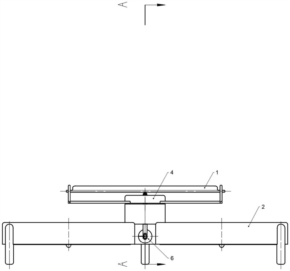
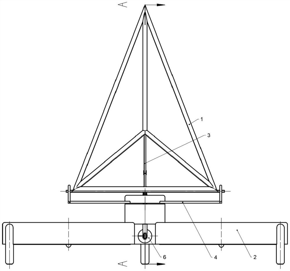
[0046] like Figure 1-Figure 4 As shown, the present invention provides a flight warning device, comprising: a warning system 1 for issuing warning signals; a flight system 2 for connecting with the warning system 1 and controlling its flight; a lift system 3 for connecting with the warning system 1 and controlling its flight Lifts and lowers relative to flight system 2 .

[0047] Specifically, the warning system 1 is used to issue sound and light warning signals, such as high-flashing warning lights / siren. The flight system 2 is used to carry the warning system 1 up to a certain distance from the bottom surface, and can be remotely controlled to fly to a designated position. Specifically, an unmanned aerial vehicle can be selected. The lift system 3 is used to control the warning system to rise and fall relative to the flight system 2. For example, when the device is not in use, the lift system 3 controls the warning system 1 to retract, reducing the size of the entire devic...

Embodiment 2

[0049] The present embodiment 2 describes the scheme to further improve the warning performance:

[0050] like Figure 1-Figure 4 As shown, a conversion system 4 is also included, which is connected to the warning system 1 and controls its rotation relative to the flight system 2 .

[0051] Specifically, most of the warning signals sent by the warning system 1 to the outside world are one-way. In order to fully transmit the warning signals to incoming vehicles from all directions where the accident occurs, the conversion system 4 is used to make the warning system 1 continuously rotate 360°; and In this way, the warning signal can also have a flickering effect. For example, in rainy and foggy weather, the light signal that remains unchanged for a long time is transmitted to the driver's line of sight, which cannot cause the driver's alertness very well. If the warning system 1 can rotate, Then, every rotation cycle will produce a similar flickering effect, so as to play a war...

Embodiment 3

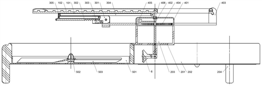
[0053] The present embodiment 3 specifically describes the structure of the flight system 2:

[0054] like Figure 5-Figure 7 As shown, the flight system 2 includes a frame 201 , a plurality of bases 202 are arranged around the frame 201 , and propellers 5 are respectively arranged in the plurality of bases 202 .

[0055] Specifically, the frame 201 is used to connect the bases 202, and is located below the warning system 1, the conversion system 4 and the lifting system 3, and undertakes the above-mentioned systems. The function of the propeller 5 is to provide flight capability. When the propeller 5 rotates to drive When the rack 201 flies, the rack 201 takes over the systems and drives them to fly. The propeller 5 includes a screw base 501, a motor 502 and a fan blade 503; the screw base 501 is fixed in the base 202, and its material is plastic or a light alloy, such as aluminum alloy; the fan blade 503 can be polyethylene, PVC and other materials; the propeller 5 is fixedl...


PUM


Abstract

The invention provides a flight warning device, and relates to the technical field of traffic safety, and the device comprises a warning system which is used for transmitting a warning signal; the flight system is connected with the warning system and controls the warning system to fly; the lifting system is connected with the warning system and controls the warning system to ascend and descend relative to the flight system. The flying system is connected with the warning system, when an automobile breaks down or encounters a motor vehicle accident and needs to be stopped emergently, a driver can stand beside the automobile to remotely control the flying system to fly up, and compared with a ground warning board, the warning board is more eye-catching and visual and does not need to walk by himself or herself to place the warning board; the danger of secondary injury caused by high-speed traffic flow is avoided, and the safety of drivers, vehicles and pedestrians is greatly improved. Moreover, the warning system is telescopically connected with the flight system through the lifting mechanism, the occupied space is small when the warning system is retracted, and the warning system is convenient to carry in a trunk.

Description

technical field [0001] The invention relates to the technical field of traffic safety, in particular to a flight warning device. Background technique [0002] After encountering a traffic accident or vehicle failure, the driver usually needs to place a warning sign at a certain position behind the car to remind the car coming from behind. [0003] A common warning sign is a small bracket and a triangular body. When placing the warning sign, people need to get off the car and walk to a dozen meters behind the car to manually place it. This process can easily lead to serial rear-end collisions, often accompanied by secondary traffic accidents. In addition, this traditional warning sign is light in weight and easily knocked down by the wind. After being knocked down, it still needs to be manually corrected. These situations are prone to secondary accidents and pose a greater safety hazard. SUMMARY OF THE INVENTION [0004] The purpose of the present invention is to provide a...

Claims


Application Information

Patent Timeline
Patent Type & Authority Applications(China)
IPC IPC(8): B60Q7/00B64C39/02G05D1/00
CPCB60Q7/00B64C39/024G05D1/0016B64U2201/20B64U2101/00
Inventor 吴文波汪家宝梁家丽胡财荣肖震申
Owner GUANGZHOU UNIVERSITY
Why Eureka
Try Eureka