Getter system in plasma plane-plate used as screen

A technology of plasma and flat plate, applied in the field of degassing system

Inactive Publication Date: 2004-04-28
SAES GETTERS SPA
View PDF4 Cites 0 Cited by
  • Summary
  • Abstract
  • Description
  • Claims
  • Application Information

AI Technical Summary

Problems solved by technology

However, once the manufacturing process is over, the MgO deposited layer will be de-energized, so this system cannot solve the problem of gradua

Method used


Image

  • Getter system in plasma plane-plate used as screen
  • Getter system in plasma plane-plate used as screen
  • Getter system in plasma plane-plate used as screen

Examples


Embodiment Construction

[0016] The following description will address the figure 1 A plasma display panel with a simple channel structure of the type shown is performed because figure 2 The structure shown with a chamber connected to a channel is substantially equivalent for the problem to be solved by the present invention.

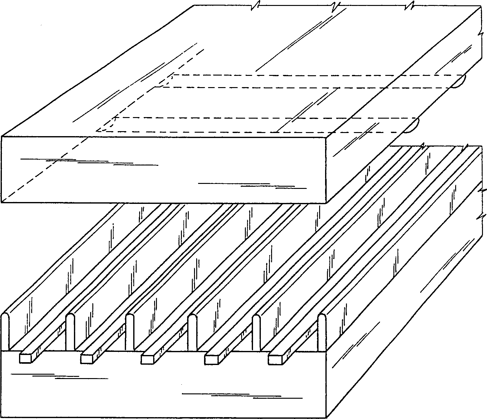
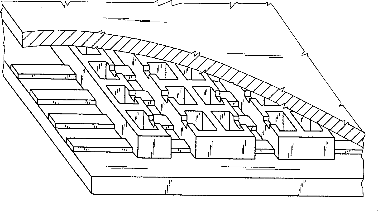
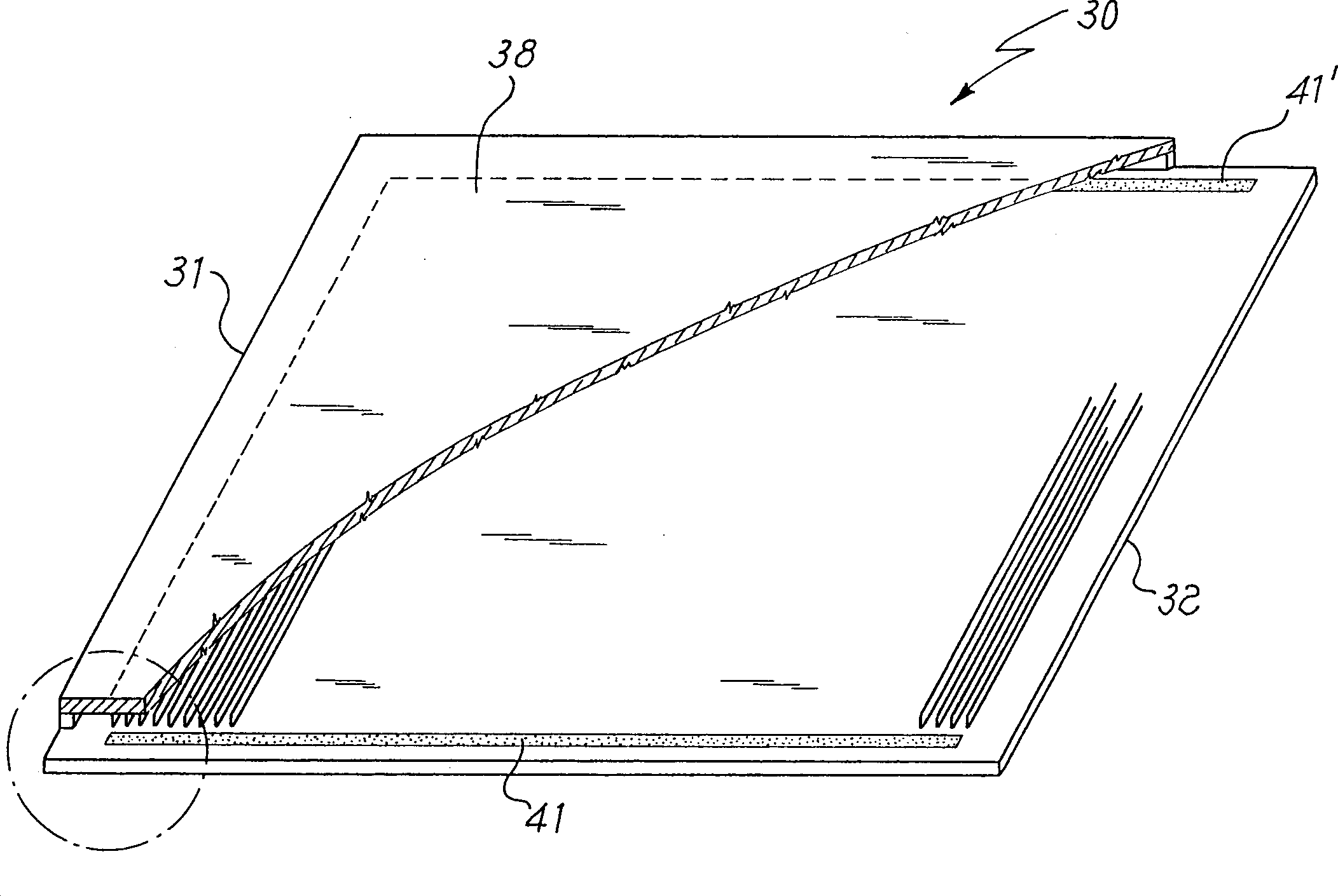
[0017] For clarity, image 3 and image 3 a only shows the main structure of the plasma display panel, and thus does not show some functional parts, such as the conductive material plating layer constituting the electrode or the fluorescent substance deposited in the channel. see image 3 and image 3 a, the plasma plate 30 is composed of a front glass part 31 and a rear glass part 32, which are sealed to each other by melting a low-melting glass paste 33 in the peripheral area 34. Contained in the interior space is a structure having channels 35, 35', ... defined by side walls 36, 36', .... The channel structure shown extends over most of the surface of the display pane...


PUM

PropertyMeasurementUnit
Particle sizeaaaaaaaaaa

Abstract

A getter system is disclosed for plasma flat panels used as screens which is composed of one or more nonvaporous-type getter devices arranged in a main channel located on at least one of band areas adjacent to panel side edges intersecting perpendicularly to the direction of secondary channels. By using the getter system of the invention a reduction of the production time is obtained, as well as a better starting quality and the keeping of the starting functional characteristics of these panels.

Description

technical field [0001] The present invention relates to a getter system for a plasma panel used as a screen. Background technique [0002] Plasma panels have been studied since about twenty years ago as possible replacements for conventional cathode ray tubes used, for example, as television screens, and it is expected that they will soon enter the market. [0003] The more common English name of these panels in the art is "plasma display panel", or "PDP" for short, and this abbreviated name is used hereinafter. [0004] A PDP is composed of two flat glass pieces, a front plate and a rear plate, whose periphery is hermetically connected with low-melting glass paste. This creates a closed space between the two panes, which is filled with a rare gas mixture and contains the functional structures described below. [0005] The working principle of the PDP is that ultraviolet light radiation generated in a rare gas when a discharge is generated therein is converted into visible...

Claims


Application Information

Patent Timeline
IPC IPC(8): H01J11/12H01J11/52
CPCH01J11/52H01J11/12
Inventor 科拉多·卡雷蒂罗伯托·M·卡洛伊马科·阿米奥迪
Owner SAES GETTERS SPA
Why Eureka
Try Eureka