
Motor rotor winding method

A technology of motor rotor and winding method, which is applied in the direction of manufacturing motor generators, electromechanical devices, electrical components, etc., can solve the problems of consumption of winding quantity, increase of winding time, high cost, etc., and achieve reduction of winding number , reduce process cost, and optimize the effect of winding mode

Pending Publication Date: 2022-07-26
TONGCHI AUTOMOBILE AIR CONDITIONER MFG
View PDF0 Cites 0 Cited by
  • Summary
  • Abstract
  • Description
  • Claims
  • Application Information

AI Technical Summary

Problems solved by technology

[0004] The traditional winding method uses the same number of slots between the motor rotor and the slot commutator, which increases the number of consumed windings and winding time, resulting in high costs

Method used


Image

  • Motor rotor winding method
  • Motor rotor winding method

Examples


Embodiment Construction

[0027] The present invention will be further described below with reference to the accompanying drawings.

[0028] like Figure 1 to Figure 2 shown,

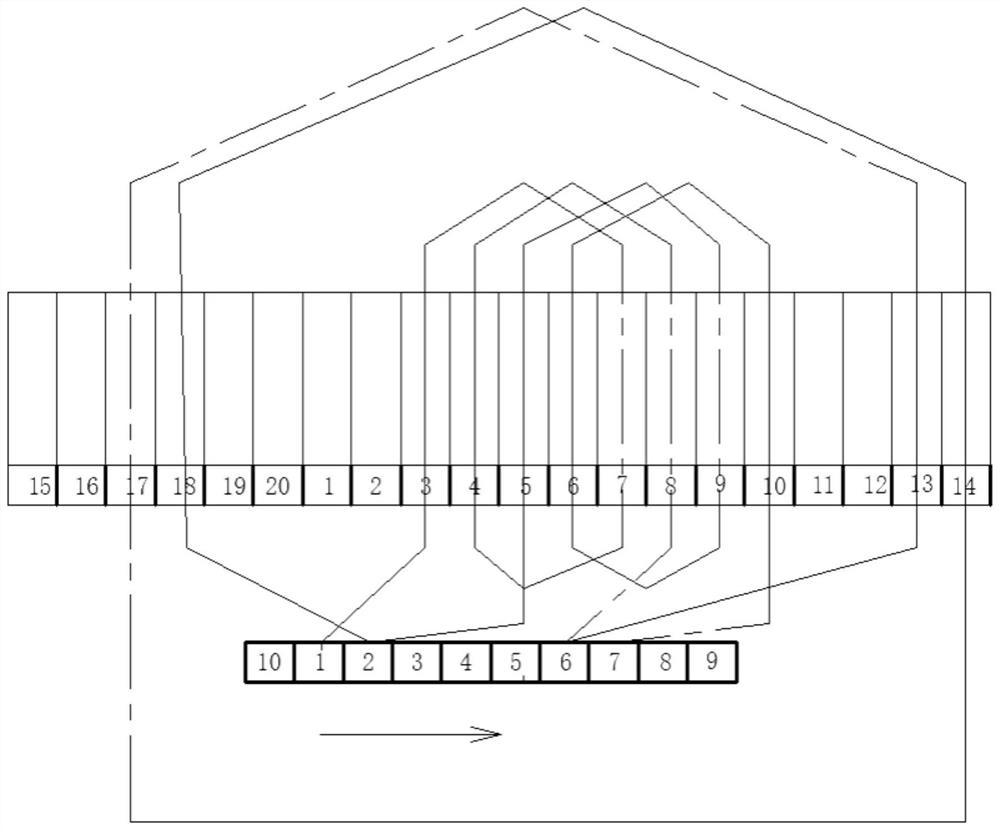
[0029] A method for winding a motor rotor, the method comprising the following steps:

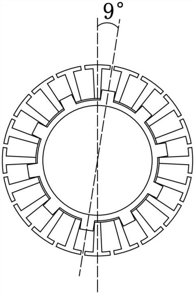
[0030] Step 1: Set up the motor rotor winding machine, the slot commutator, the motor rotor and the winding material, in which 20 slots are arranged on the motor rotor and 10 slots are arranged on the slot commutator. By making the slot commutation The number of slots of the motor is smaller than the number of slots of the motor rotor. Using a new winding method to reduce the number of windings can reduce the process cost.

[0031] Step 2: Install the winding material, the motor rotor and the slot commutator on the motor rotor winding machine. In the second step, the slot commutator is detachably connected to the motor rotor. When set on the motor rotor, keep the included angle between the center line of the motor rotor and the center line...


PUM

PropertyMeasurementUnit
Angleaaaaaaaaaa

Abstract

The invention relates to the technical field of motor rotor winding, in particular to a motor rotor winding method. The method comprises the following steps of 1, arranging a motor rotor winding machine, a groove type commutator, a motor rotor and a winding material; 2, the winding material, the motor rotor and the groove type commutator are installed on a motor rotor winding machine, and grooves are formed in the groove type commutator and the motor rotor; and 3, the motor rotor winding machine starts to wind the winding material on the groove type commutator and the motor rotor, the groove type commutator and the motor rotor jointly rotate along the axis of the motor rotor to form a plurality of loops, and the grooves of the groove type commutator and the motor rotor starting to wind are represented by n, and n is larger than or equal to 1 and smaller than or equal to 10. The method has the advantages of optimizing the winding mode, reducing the number of windings and reducing the process cost.

Description

technical field [0001] The invention relates to the technical field of motor rotor winding, and more particularly relates to a motor rotor winding method. Background technique [0002] Motor rotor: Also the rotating part in the motor. The motor is composed of two parts, the rotor and the stator. It is used to realize the conversion device between electrical energy and mechanical energy and mechanical energy and electrical energy. The motor rotor is divided into the motor rotor and the generator rotor. [0003] The rotor of the motor needs to be wound, so as to generate a magnetic field when it is energized, and interact with the stator to rotate. When the number of winding turns is more, the generated magnetic field is larger. [0004] The traditional winding method uses the same number of slots between the motor rotor and the slot commutator, which increases the number of windings consumed and the winding time, resulting in high costs. SUMMARY OF THE INVENTION [0005]...

Claims


Application Information

Patent Timeline
IPC IPC(8): H02K15/09
CPCH02K15/09
Inventor 方必祥张建华
Owner TONGCHI AUTOMOBILE AIR CONDITIONER MFG
Learn More