Stroboflash-free active power factor correcting circuit applied to LED drive

A technology for driving and correcting circuits for LEDs, which is applied to the layout of electric lamp circuits, conversion devices for output power, light sources, etc. It can solve problems such as complex structures and high production costs, and achieve the effects of simplified circuits, low-voltage breakdown, and wide application range

Active Publication Date: 2015-04-29
CRM ICBG (WUXI) CO LTD
View PDF6 Cites 1 Cited by
  • Summary
  • Abstract
  • Description
  • Claims
  • Application Information

AI Technical Summary

Problems solved by technology

But there are also disadvantages of complex structure, and it can only be applied to circuits with isolation architecture, including 4 diodes, and the transformer includes 3 coils, and the production cost is high

Method used


Image

  • Stroboflash-free active power factor correcting circuit applied to LED drive
  • Stroboflash-free active power factor correcting circuit applied to LED drive
  • Stroboflash-free active power factor correcting circuit applied to LED drive

Examples


Embodiment Construction

[0024] The present invention will be further described below in conjunction with accompanying drawing and embodiment:

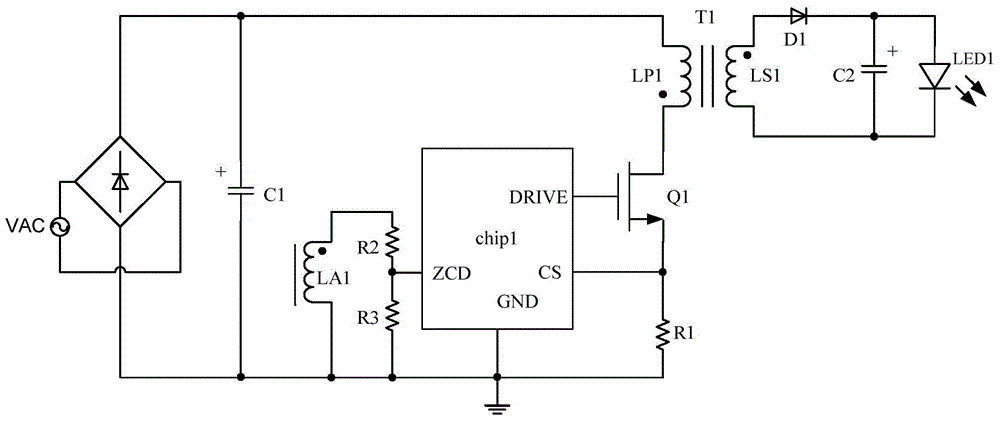
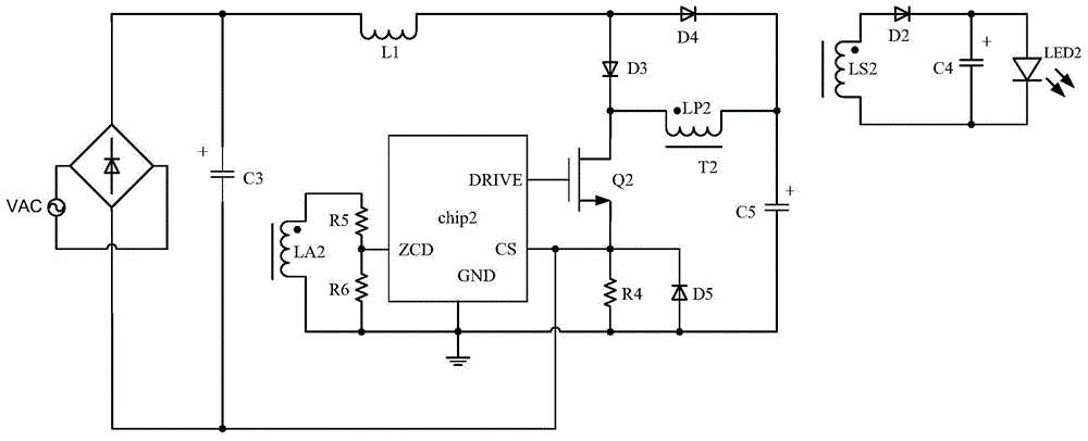
[0025] A flicker-free active power factor correction circuit applied to LED driving: in an isolated circuit structure:

[0026] see Figure 4~5 As shown, it includes rectifier circuit, filter capacitor, first stage inductor L2, control chip, power tube Q3, transformer T3, energy storage capacitor C7, first switch tube D7, second switch tube D8 and LED load circuit, the first stage One end of the inductor L2 is connected to the positive output terminal of the bridge rectifier circuit, and the other end is connected to the drain of the power transistor Q3 and the positive electrode of the energy storage capacitor C7; the transformer T3 includes two coils, primary and secondary, and one end of the primary coil LP3 of the transformer T3 passes through the inductor current The sampling resistor R7 is connected to the source of the power tube Q3, the other end of ...


PUM


Abstract

The invention discloses a stroboflash-free active power factor correcting circuit applied to LED drive. The stroboflash-free active power factor correcting circuit applied to LED drive comprises a rectifying circuit, a filtering capacitor, a first-level inductor, a control chip, a power tube, a transformer and an LED load circuit and is characterized by further comprising an energy storage capacitor, a first switch tube and a second switch tube, wherein one end of the first-level inductor is connected with the output end of the rectifying circuit, the other end of the first-level inductor is connected with the drain electrode of the power tube and the positive pole of the energy storage capacitor, the transformer comprises at least one main coil, one end of the main coil of the transformer is connected with the source electrode of the power tube through a sampling resistor, and the other end of the main coil of the transformer is in parallel connection with the negative pole of the energy storage capacitor. The stroboflash-free active power factor correcting circuit provides direct current constant source through the energy storage capacitor, two times of ripple waves of power frequency are eliminated, no stroboflash is output while power factor correction, the circuit is simplified, and cost is reduced.

Description

technical field [0001] The invention relates to an LED driving circuit, in particular to a flicker-free active power factor correction circuit applied to LED driving. Background technique [0002] Due to the advantages of low energy consumption, long service life and high luminous efficiency, LED lamps have been widely used in lighting and decoration fields. Generally, the LED drive circuit adopts switching power supply drive technology, and in order to reduce the harmonic pollution to the power grid and improve the power factor of the input side, the application of power factor correction technology in LED lamps is gradually becoming popular. [0003] Generally, LED drive circuits use constant current to drive LED loads. The traditional LED drive circuit with active power factor correction function has a large power frequency current ripple in the output, which causes the human eye to feel the stroboscopic phenomenon of the LED light, which is especially serious when using...

Claims


Application Information

Patent Timeline
Patent Type & Authority Applications(China)
IPC IPC(8): H02M1/42H05B37/02
CPCH02M1/4258H05B47/10Y02B70/10
Inventor 夏虎
Owner CRM ICBG (WUXI) CO LTD
Why Eureka
Try Eureka