Three-phase synchronous motor DC converter

A DC converter, three-phase synchronization technology, applied in motors, excitation or armature current control, electric vehicles, etc., can solve the problems of difficult to achieve closed-loop, low speed accuracy requirements, difficult instantaneous control and other problems

Active Publication Date: 2022-05-31
武汉豪岩照明电子有限公司
View PDF8 Cites 0 Cited by
  • Summary
  • Abstract
  • Description
  • Claims
  • Application Information

AI Technical Summary

Problems solved by technology

[0002] Brushless DC or synchronous motors are widely used. A large number of electric vehicles, tools, etc., mainly require a certain speed for continuous load applications, but the speed accuracy is not high, such as fans, water pumps, etc. are mostly open-loop control, variable loads The application mainly has higher requirements on the motor speed, such as household appliance dryers, compressors, oil pumps in automobiles, etc., and most industrial control motors are used for positioning applications, which have special requirements for dynamic response and torque. Practical brushless motors are not limited to signal sensing, because of their different components, it is not only related to performance indicators, noise and vibration, reliability and service life, but also involves manufacturing costs and product costs. There are many varieties of brushless motors for new motor applications , but the excellent performance is limited by the price, the driving motor and performance requirements are difficult to form a convenient application, because the brushless motor is free of carbon brush maintenance, in order to achieve the performance equivalent to the DC motor in terms of characteristics, complex control technology must be used, while the traditional The BLDCM control circuit is mostly controlled by a single-chip microcomputer. Due to the limitation of CPU operation speed, it is difficult to achieve instantaneous control, especially in vehicle applications. It is difficult to achieve closed-loop

Method used


Image

  • Three-phase synchronous motor DC converter
  • Three-phase synchronous motor DC converter
  • Three-phase synchronous motor DC converter

Examples


Embodiment Construction

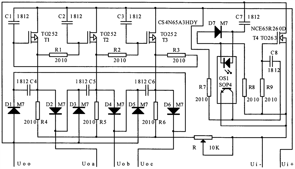
[0008] like figure 1 Shown is the circuit diagram of the open-loop DC converter applying the synchronous motor of the present invention. In the figure, T1, T2, T3 are three P-channel field effect transistors, TO252 is a chip package model, capacitors C1, C2, C3 and resistors R4, R5, R6 is a three-phase oscillating RC, capacitor 1812 and resistor 2010 are SMD package models, R1, R2, R3 are discharge current limiting resistors, C4, C5, C6 are auxiliary output capacitors, and diodes D1--D6 are the main and auxiliary output current directions Control, M7 is a diode chip package model, output three-phase from low to high double-cross unidirectional wave, R is a speed trimmer potentiometer, T4 is a high-frequency oscillation loading wave N-channel field effect transistor, R7, R8 and C7, C8 It is high frequency oscillation RC, R9 is T4 gate resistor, optocoupler OS1 is SOP4 chip package, output Uoa, Uob, Uoc three-phase, and Uoo is 0-wire open-loop three-phase four-wire star connecti...


PUM


Abstract

The invention relates to a three-phase synchronous motor DC converter, which can be widely used in electric vehicles, model machines, axial flow fans, fruit juice machines, rechargeable electric tools, solar powered water pumps and other fields of power motor drive, T1, T2, T3 in the figure It is three P-channel field effect transistors, capacitors C1, C2, C3 and resistors R4, R5, R6 are three-phase oscillating RC, R1, R2, R3 are discharge current limiting resistors, C4, C5, C6 are auxiliary output capacitors, diodes D1‑‑D6 is the main and auxiliary output current direction control, the output three-phase from low to high double cross one-way wave, R is the speed trimming potentiometer, T4 is the high-frequency oscillation loading wave N-channel field effect transistor, R7, R8 and C7 , C8 is high-frequency oscillation RC, R9 is T4 grid resistance, D7 of optocoupler OS1 is a discharge diode, output Uoa, Uob, Uoc three-phase, and Uoo is an open-loop three-phase four-wire star connection of 0 line.

Description

technical field [0001] The invention relates to a three-phase synchronous motor DC converter, which can be widely used in electric vehicles, model machines, axial fans, juice machines, rechargeable electric tools, solar powered water pumps and other fields of power motor drive. Background technique [0002] Brushless DC or synchronous motors are widely used, a large number of electric vehicles, tools, etc., the continuous load application mainly only needs a certain speed, but the speed accuracy is not high, such as fans, water pumps, etc. are mostly open-loop control, variable load The application mainly has higher requirements on the motor speed, such as household appliances dryers, compressors, oil pumps in automobiles, etc. are relatively high, while most industrial control motors are positioning applications, which have special requirements for dynamic response and torque. Practical brushless motors are not limited to signal sensing. Because of their different compositi...

Claims


Application Information

Patent Timeline
Patent Type & Authority Patents(China)
IPC IPC(8): H02P7/28
CPCH02P7/28Y02T10/64
Inventor 不公告发明人
Owner 武汉豪岩照明电子有限公司
Why Eureka
Try Eureka