Nuclear magnetic resonance head supporting device for imaging department

A technology of nuclear magnetic resonance and support devices, applied in medical science, diagnosis, diagnostic recording/measurement, etc., can solve the problems of lack of neck support and neck pain in patients, and achieve the effect of avoiding shaking and reducing soreness

Pending Publication Date: 2022-07-29
FIRST AFFILIATED HOSPITAL OF KUNMING MEDICAL UNIV
View PDF0 Cites 0 Cited by
  • Summary
  • Abstract
  • Description
  • Claims
  • Application Information

AI Technical Summary

Problems solved by technology

[0005] The purpose of the present invention is to solve the shortcomings of lack of support for the patient's neck in the prior art, thus making the patient's

Method used


Image

  • Nuclear magnetic resonance head supporting device for imaging department
  • Nuclear magnetic resonance head supporting device for imaging department
  • Nuclear magnetic resonance head supporting device for imaging department

Examples


Example Embodiment

[0025] Example 1

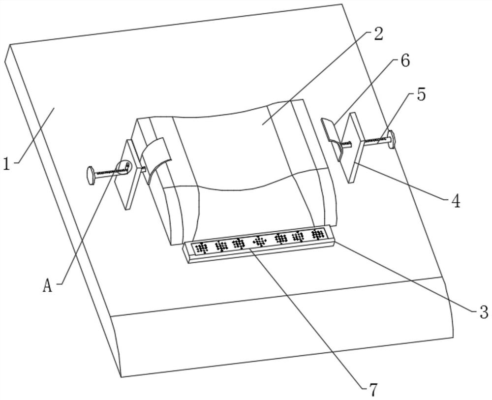
[0026] like Figure 1-5 As shown in the figure, an imaging department MRI head support device proposed by the present invention includes a base 1, a pillow 2 is installed on the outside of the base 1, a support block 3 is installed on the outside of the base 1, and a support massage is installed inside the support block 3 mechanism, the interior of the pillow 2 is provided with a fixed airbag 10;

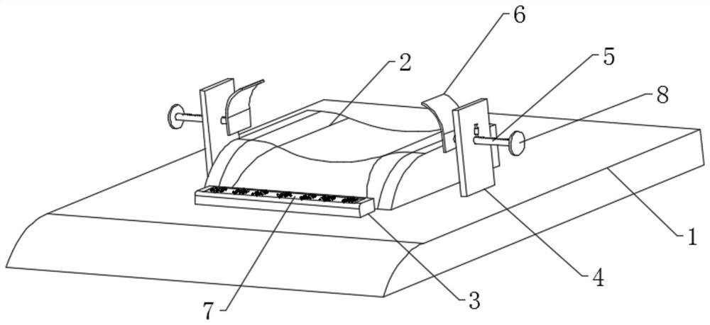
[0027] A fixed plate 4 is symmetrically installed on the outside of the base 1, and a positioning mechanism for fixing the position of the head is arranged on the outside of the fixed plate 4. The positioning mechanism includes a transmission rod 5 slidably connected to the outside of the fixed plate 4. 4. A side positioning plate 6 is installed on one end of the transmission rod 5 close to the pillow 2, a hollow tube 13 is installed on the outside of the fixed plate 4, and the inner part of the hollow tube 13 is slidably connected to a limit rod 14;

[0028] In...

Example Embodiment

[0033] Embodiment 2

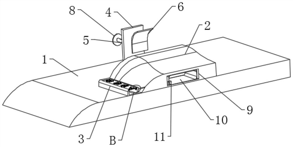
[0034] like Figure 1-5 As shown, based on the first embodiment, a placement cavity 9 is opened inside the pillow 2, and a fixed airbag 10 is installed in the interior of the placement cavity 9, and the support groove 15 and the fixed airbag 10 in the massage mechanism are connected by an air intake pipe 11. The support airbag 7 is installed inside the support groove 15;

[0035] A plurality of connecting grooves 16 are provided on the outside of the support airbag 7 , and massage contacts 17 are installed inside the connecting grooves 16 , and the massage contacts 17 communicate with the inside of the support block 3 .

[0036] In this embodiment, when the patient is lying flat on the pillow 2 during work, because the material of the pillow 2 is relatively soft, the fixed airbag 10 is squeezed under the action of the patient's own head weight, so that the inner part of the fixed airbag 10 is squeezed. The gas enters the inside of the support groove 15 ...


PUM


Abstract

The invention discloses a nuclear magnetic resonance head supporting device for the imaging department. According to the technical scheme, the nuclear magnetic resonance head supporting device comprises a base, a pillow is installed outside the base, a supporting block is installed outside the base, a supporting massage mechanism is arranged in the supporting block, and a fixed air bag is arranged in the pillow; fixing plates are symmetrically installed outside the base, positioning mechanisms for fixing the head position are arranged outside the fixing plates, each positioning mechanism comprises a transmission rod slidably connected to the outside of the corresponding fixing plate, the transmission rods penetrate through the fixing plates, side face positioning plates are installed at the ends, close to the pillow, of the transmission rods, and hollow pipes are installed outside the fixing plates; through cooperative use of a transmission rod, a side face positioning plate, a limiting hole and a hollow pipe in the positioning mechanism, the position of the side face positioning plate can be accurately adjusted, so that patients with different head sizes can be accurately clamped, and shaking of the head in the nuclear magnetic resonance imaging detection process is avoided; and stable operation of nuclear magnetic resonance imaging is ensured.

Description

technical field [0001] The invention relates to the technical field of medical head support, in particular to an imaging department nuclear magnetic resonance head support device. Background technique [0002] Magnetic resonance imaging is based on the different attenuation of the released energy in different structural environments inside the material. By detecting the emitted electromagnetic waves by applying a gradient magnetic field, the position and type of the nuclei that constitute the object can be known, and the object can be drawn accordingly. Internal structural image. [0003] When performing an MRI test on a patient, the patient is required to lie flat on the test bed and keep breathing steady. [0004] The traditional MRI head support device lacks support for the patient's neck during use, so that the patient's neck is sore during the MRI test, and it is difficult to effectively adjust the patient's head according to the size of the patient's head. Therefore,...

Claims


Application Information

Patent Timeline
IPC IPC(8): A61B5/055A61B5/00
CPCA61B5/055A61B5/702
Inventor 谷何一何波莫茵李宗芳鲁毅易文芳高超曾一真史一欣
Owner FIRST AFFILIATED HOSPITAL OF KUNMING MEDICAL UNIV
Why Eureka
Try Eureka