Supercharge Your Innovation With Domain-Expert AI Agents!

Dialysis tube fixing device for nephrology department nursing

A technology for fixing devices and dialysis tubes, applied in dialysis systems, catheters, etc., can solve the problems of inconvenient use and cumbersome operation of dialysis tube fixing devices, and achieve the effects of complete functions, reasonable and simple structure, and low production cost

Inactive Publication Date: 2022-07-29
NO 2 PEOPLES HOSPITAL HUAIAN CITY
View PDF0 Cites 0 Cited by
  • Summary
  • Abstract
  • Description
  • Claims
  • Application Information

AI Technical Summary

Problems solved by technology

[0003] The purpose of the present invention is to provide a dialysis tube fixing device for nephrology nursing in order to solve the above problems, which solves the problem that the dialysis tube fixing device is very inconvenient to use and complicated to operate

Method used


Image

  • Dialysis tube fixing device for nephrology department nursing
  • Dialysis tube fixing device for nephrology department nursing
  • Dialysis tube fixing device for nephrology department nursing

Examples


Embodiment 1

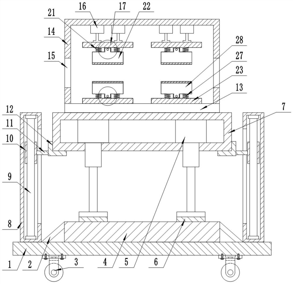
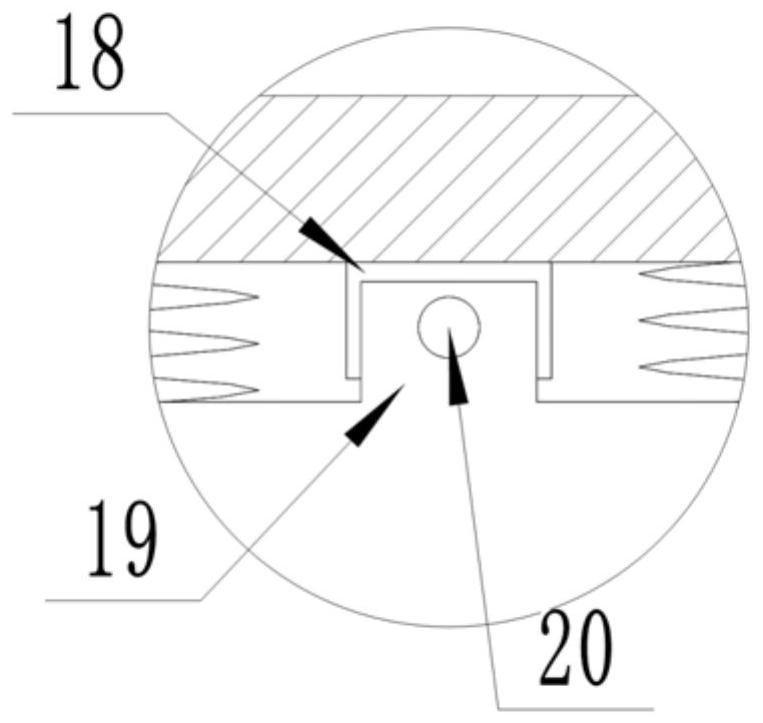
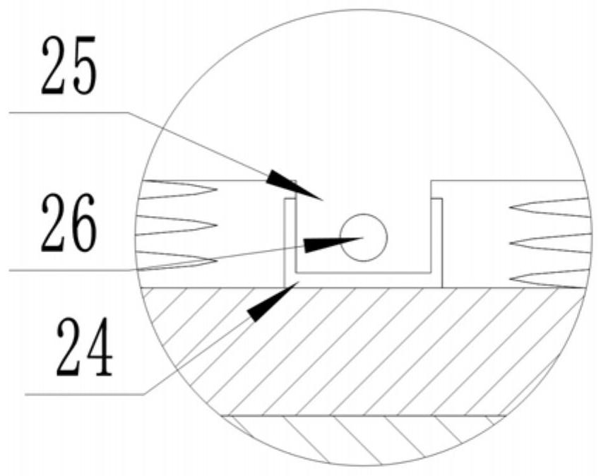
[0022] like Figure 1 to Figure 5 As shown, this specific embodiment adopts the following technical solutions: a dialysis tube fixing device for nephrology nursing, comprising a base 1, a support plate 2, a universal wheel 3, a mounting plate 4, a hydraulic cylinder 5, a buffer pad 6, a lift box 7. Sliding rod box 8, sliding rod 9, slider 10, connecting rod 11, L-shaped support plate 12 and limiting device; several universal wheels 3 are fixedly connected around the lower surface of the base 1, so as to facilitate movement; The mounting plate 4 is fixedly connected to the center of the upper end of the base 1; both sides of the mounting plate 4 are fixedly connected to the base 1 through the support plates 2 on both sides; the lifting box 7 is located directly above the mounting plate 4; Hydraulic cylinders 5 are fixedly connected to both sides of the top of the chamber of the box 7, so as to adjust the height; the output end of the hydraulic cylinder 5 is fixedly connected to...

Embodiment 2

[0025] like Figure 1 to Figure 5 As shown, this specific embodiment adopts the following technical solutions: a dialysis tube fixing device for nephrology nursing, comprising a base 1, a support plate 2, a universal wheel 3, a mounting plate 4, a hydraulic cylinder 5, a buffer pad 6, a lift box 7. Sliding rod box 8, sliding rod 9, slider 10, connecting rod 11, L-shaped support plate 12 and limiting device; several universal wheels 3 are fixedly connected around the lower surface of the base 1, so as to facilitate movement; The mounting plate 4 is fixedly connected to the center of the upper end of the base 1; both sides of the mounting plate 4 are fixedly connected to the base 1 through the support plates 2 on both sides; the lifting box 7 is located directly above the mounting plate 4; Hydraulic cylinders 5 are fixedly connected to both sides of the top of the chamber of the box 7, so as to adjust the height; the output end of the hydraulic cylinder 5 is fixedly connected to...


PUM


Abstract

The invention discloses a dialysis tube fixing device for nephrology department nursing. The dialysis tube fixing device comprises a base, a supporting plate, universal wheels, a mounting plate, a hydraulic cylinder, a buffer pad, a lifting box, a sliding rod box, a sliding rod, a sliding block, a connecting rod, an L-shaped supporting plate and a limiting device. The device is reasonable and simple in structure, low in production cost, convenient to install and complete in function, and the hydraulic cylinder, the buffer pad, the lifting box, the sliding rod box, the sliding rod, the sliding block, the connecting rod and the L-shaped supporting plate are matched with one another, so that the overall height of the device can be effectively and stably adjusted to be suitable for patients of different heights; through mutual cooperation of the pneumatic cylinder, the first supporting plate, the first fixing block, the first stabilizing block, the second bolt, the first spring, the first clamping block, the second supporting plate, the second fixing block, the second stabilizing block, the third bolt, the second spring and the second clamping block, a tube can be rapidly fixed, and dialysis of the tube is facilitated.

Description

technical field [0001] The invention relates to the technical field of dialysis tube fixing, in particular to a dialysis tube fixing device for nephrology nursing. Background technique [0002] In the process of hemodialysis, the dialysis tube is of great significance. In the existing dialysis treatment process, medical personnel need to fix the dialysis tube when performing renal dialysis on patients, so as to ensure the efficiency of dialysis. The dialysis tube falls off or shakes, which has a serious impact on the dialysis process and the life of the patient. The existing dialysis tube fixing device is very inconvenient to use, and the operation is cumbersome, and the doctor needs to hold the dialysis tube for a long time. Therefore, a dialysis tube fixing device for nephrology nursing is proposed. SUMMARY OF THE INVENTION [0003] The purpose of the present invention is to provide a dialysis tube fixing device for nephrology nursing in order to solve the above problem...

Claims


Application Information

Patent Timeline
IPC IPC(8): A61M25/02A61M1/14
CPCA61M25/02A61M1/14A61M2025/024A61M2025/028
Inventor 刘军
Owner NO 2 PEOPLES HOSPITAL HUAIAN CITY
Features
  • R&D
  • Intellectual Property
  • Life Sciences
  • Materials
  • Tech Scout
  • Unparalleled Data Quality
  • Higher Quality Content
  • 60% Fewer Hallucinations
Learn More