Optical fiber laser cutting machine with positioning mechanism

A fiber laser and positioning mechanism technology, applied in laser welding equipment, metal processing equipment, welding equipment, etc., can solve the problems of inability to locate, affect production efficiency, and lack of convenient positioning mechanism, etc., achieve strong practicability and improve mobile stability , Good positioning and clamping effect

Inactive Publication Date: 2022-07-29
深圳市大鹏激光科技有限公司
View PDF0 Cites 0 Cited by
  • Summary
  • Abstract
  • Description
  • Claims
  • Application Information

AI Technical Summary

Problems solved by technology

There is no convenient and effective positioning mechanism on the workbench of the optical fiber laser cutting machine in the prior art, and it cannot be quickly positioned when cutting small plates to be cut, which affects production efficiency, and sometimes the cutting accuracy cannot be guaranteed. Therefore, a A fiber laser cutting machine with a positioning mechanism to meet the needs of use

Method used


Image

  • Optical fiber laser cutting machine with positioning mechanism
  • Optical fiber laser cutting machine with positioning mechanism
  • Optical fiber laser cutting machine with positioning mechanism

Examples


Embodiment 1

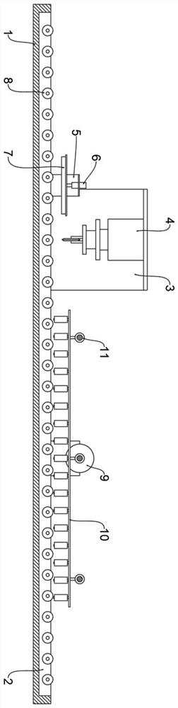
[0019] see figure 1 , a fiber laser cutting machine with a positioning mechanism, including a workbench 1, a groove body 2 is arranged on the workbench 1, a number of transport rollers 8 are evenly arranged in the groove body 2, and the workbench 1 is provided with A first mounting plate 3, a cutting device 4 is provided on the first mounting plate 3, a positioning assembly 10 is provided on the worktable 1 at a position on one side of the first mounting plate 3, and a side of the positioning assembly 10 is provided There is an adjusting assembly 9, the adjusting assembly 9 is used to drive the positioning assembly 10 to operate, and a fixing assembly is provided at the other side of the first mounting plate 3, and the positioning assembly 10 is used to clamp the side of the plate The fixing assembly is used for cooperating with the transport roller 8 to fix the position of the plate during cutting.

[0020] see figure 1 , 3 , the positioning assembly 10 includes a movable ...

Embodiment 2

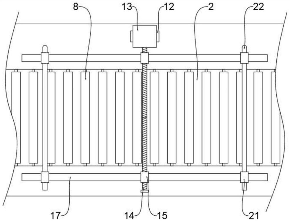
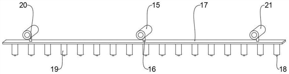
[0022] see figure 1 , 2 On the basis of the first embodiment, the adjustment assembly 9 includes a mounting seat 12 arranged on the workbench 1, a driving member 13 arranged on the mounting seat 12, and a threaded rod 14 connected to the extension of the driving member 13. And the two threaded sleeves 15 symmetrically arranged on the threaded rod 14, the damaged threaded rod 14 has two sets of external threads with symmetrical and opposite thread directions, and the outer walls of the two threaded sleeves 15 pass through the first connecting rod 16. They are respectively connected with the two movable plates 17. In this embodiment, rail assemblies 11 are provided on both sides of the adjustment assembly 9. The rail assemblies 11 include positioning rods 22 arranged on the The two positioning sleeves 21 on the positioning plate, and the outer walls of the two positioning sleeves 21 are respectively connected with the two movable plates 17 through the second connecting rod 20 ....


PUM


Abstract

The invention relates to the related technical field of cutting machines, in particular to an optical fiber laser cutting machine with a positioning mechanism, which comprises a working table, a cutting assembly is arranged on the working table through a first mounting plate, and one side of the cutting assembly is provided with an adjusting assembly to be matched with a positioning assembly to position and clamp the side part of a plate; the positioning assembly clamps the side portion of a plate by arranging a movable plate to be matched with a plurality of pressing rollers, feeding and conveying of the plate are not affected, the other side of the cutting assembly is provided with a fixing assembly to improve the moving stability of the movable plate, and one end of the plate in the cutting state is fixed by arranging the fixing assembly; and the plates cannot be accidentally separated from the conveying rollers after being cut, so that the positioning and clamping effects on the plates are improved.

Description

technical field [0001] The invention relates to the related technical field of cutting machines, in particular to a fiber laser cutting machine with a positioning mechanism. Background technique [0002] Fiber laser cutting machine (2KW) can efficiently cut the plate to be cut placed on the carrier plate. There is no convenient and effective positioning mechanism on the worktable of the fiber laser cutting machine in the prior art, and it cannot be quickly positioned when cutting a small plate to be cut, which affects the production efficiency, and sometimes the cutting accuracy cannot be guaranteed. Therefore, a method is proposed. A fiber laser cutting machine with a positioning mechanism to meet the needs of use. SUMMARY OF THE INVENTION [0003] The purpose of the present invention is to provide a fiber laser cutting machine with a positioning mechanism to solve the above-mentioned problems in the background art. [0004] To achieve the above object, the present inve...

Claims


Application Information

Patent Timeline
Patent Type & Authority Applications(China)
IPC IPC(8): B23K26/38B23K26/70
CPCB23K26/38B23K26/702
Inventor 汤鹏飞汤万飞
Owner 深圳市大鹏激光科技有限公司
Why Eureka
Try Eureka