Wireless charging annular magnet assembling device

A ring magnet and assembly device technology, applied in assembly machines, metal processing equipment, connecting components, etc., can solve the problems of damaged fixing stickers, excessive waste, and prolong assembly time, so as to reduce labor intensity, reduce consumables costs, and improve The effect of production assembly efficiency

Active Publication Date: 2022-07-29
浙江英洛华引力科技有限公司
View PDF7 Cites 1 Cited by
  • Summary
  • Abstract
  • Description
  • Claims
  • Application Information

AI Technical Summary

Problems solved by technology

[0002]In the existing wireless charger, there are a plurality of single magnets arranged in a circular array, which requires workers to fix the plurality of magnets on the sticky stickers on the outer edge. And realize the arrangement of multiple magnets in a circular array. After the magnets are arranged and fixed with the fixed stickers, the fixed stickers with the magnets fixed are sent to the next station to magnetize the magnets; due to the stickiness of the fixed stickers, once the position of the magnet is If the placement is wrong, removing the magnet from the fixing sticker will easily cause the fixing sticker to be damaged, which will not only prolong the assembly time, but also easily cause more waste due to the damage of the fixing sticker

Method used


Image

  • Wireless charging annular magnet assembling device
  • Wireless charging annular magnet assembling device
  • Wireless charging annular magnet assembling device

Examples


Embodiment Construction

[0031] The present invention will be further described below according to the accompanying drawings and specific embodiments.

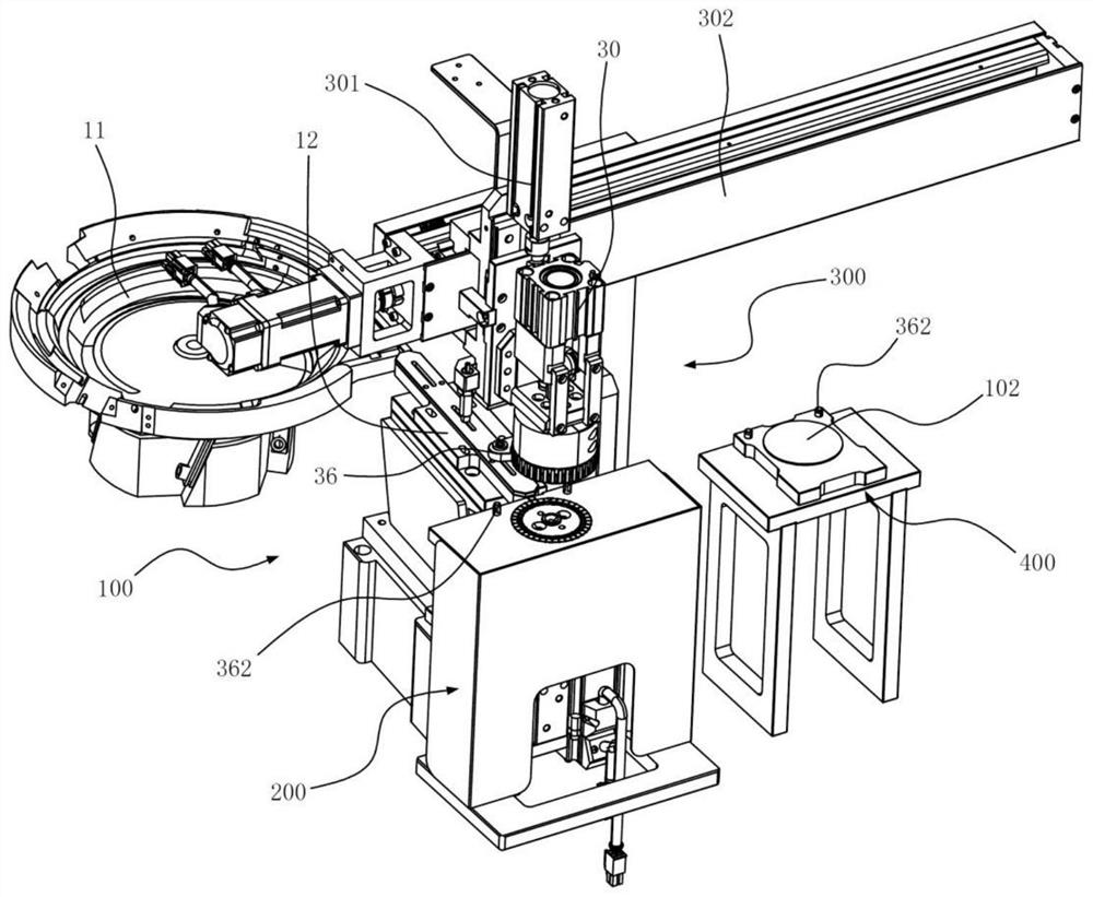
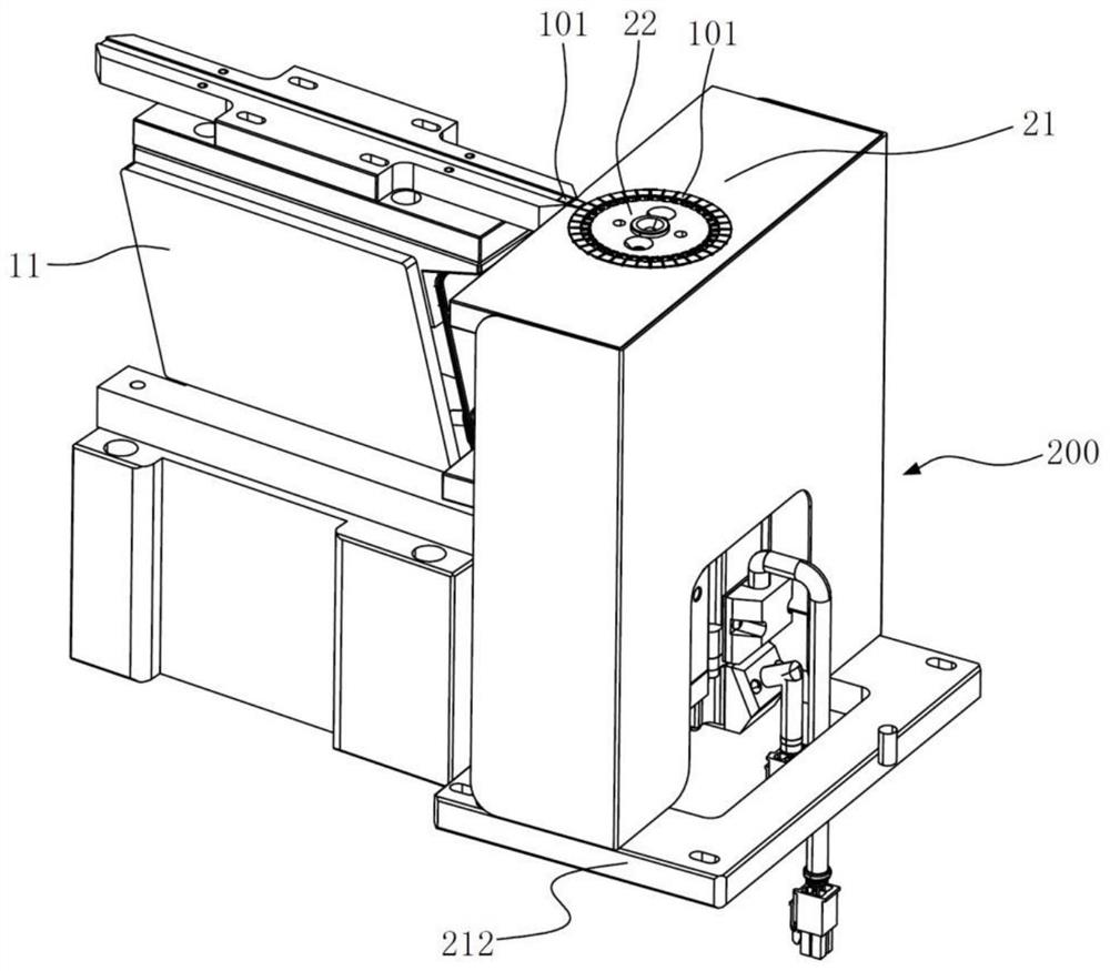
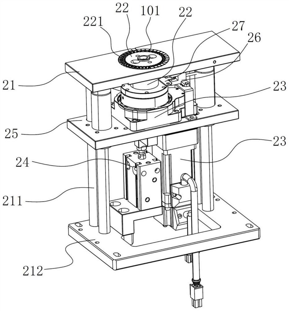
[0032] Depend on figure 1 As shown, this embodiment discloses a wireless charging ring magnet assembly device, including a feeding assembly 100 for realizing the feeding of the magnet workpiece 101, a positioning assembly 200 for realizing the arrangement of the magnet workpiece 102, The gripping assembly 300 for moving the magnet workpiece 101 , and the table 400 for placing the fixing sticker 102 . The grasping assembly 300 includes a gripper, the gripper is fixed on the lift plate of the lift cylinder 301, the lift cylinder 301 is fixed on the traverse plate of the traverse cylinder 302, and the positioning assembly 200 and the worktable 400 are located on the front side of the traverse cylinder and are parallel to each other. Set side by side.

[0033] The feeding assembly 100 includes a vibrating plate 11 and a linear vibrating plate 12. The li...


PUM


Abstract

The invention relates to automatic production assembly equipment, in particular to a wireless charging annular magnet assembly device. A wireless charging annular magnet assembling device is characterized in that the wireless charging annular magnet assembling device comprises a feeding assembly, a positioning assembly, a grabbing assembly and a workbench, the feeding assembly comprises a conveying rail, the grabbing assembly comprises a clamping jaw, the clamping jaw can move between the positioning assembly and the workbench, the positioning assembly comprises a fixing plate and a rotating driver, and the rotating driver is arranged on the fixing plate. A containing groove with an upward opening is formed in the fixing plate, an inner positioning piece is arranged in the containing groove, the inner positioning piece is provided with a plurality of positioning grooves with lateral openings, the positioning grooves are evenly distributed in the inner positioning piece with the vertical axis as the center, and the fixing plate is provided with a feeding guide groove which is provided with a lateral opening and enables the positioning grooves to be communicated with the conveying rail. The device has the advantages that the production and assembly efficiency can be improved, the labor intensity of workers is reduced, the consumable cost is reduced, and follow-up procedures are facilitated.

Description

technical field [0001] The invention relates to an automatic production and assembly equipment, in particular to a wireless charging ring magnet assembly device. Background technique [0002] The existing wireless chargers are provided with a plurality of magnet units arranged in a circular array, which requires workers to fix the plurality of magnets on the outer edge of the adhesive fixing sticker, and realize the arrangement of the plurality of magnets in a circular array, complete the arrangement of the magnets and fix them together. After the sticker is fixed, send the fixed sticker with the magnet fixed to the next station to magnetize the magnet; because the fixed sticker is sticky, once the magnet is placed in the wrong position, removing the magnet from the fixed sticker will easily lead to the fixed sticker. If it is damaged, it will not only prolong the assembly time, but also easily cause more waste due to damage to the fixing stickers. SUMMARY OF THE INVENTION...

Claims


Application Information

Patent Timeline
Patent Type & Authority Applications(China)
IPC IPC(8): B23P21/00B23P19/00F16B11/00
CPCB23P21/00B23P19/001B23P19/002B23P19/006B23P19/00F16B11/006
Inventor 魏侃侃刘明明
Owner 浙江英洛华引力科技有限公司
Why Eureka
Try Eureka