Supercharge Your Innovation With Domain-Expert AI Agents!

Die with secondary ejection angle ejector structure

A secondary ejection and secondary ejection technology, applied in the field of molds, can solve the problems of reducing the design size of the mold, inconvenient disassembly, and high cost, and achieve the effects of reducing the injection molding cycle, facilitating disassembly and maintenance, and reducing the production cost of injection molding

Pending Publication Date: 2022-07-29
森骏卓越精密智造(深圳)有限公司
View PDF0 Cites 0 Cited by
  • Summary
  • Abstract
  • Description
  • Claims
  • Application Information

AI Technical Summary

Problems solved by technology

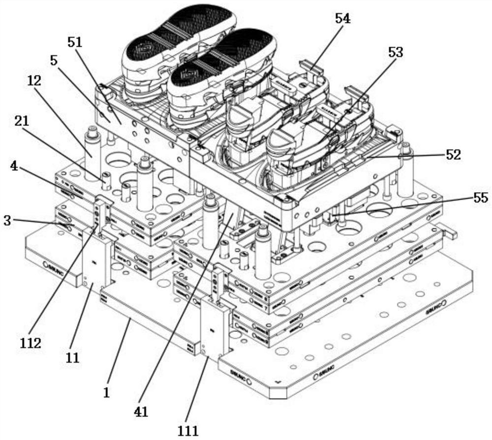
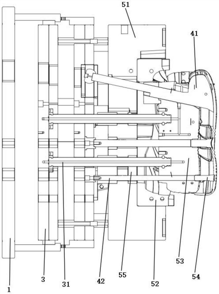
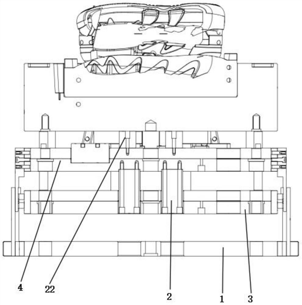
[0007] In order to solve the problems in the prior art, the present invention provides a mold with a secondary ejection slanted top structure. By setting the secondary ejection slanted top structure in the mold, the driving device can drive the first thimble plate, the second thimble The plate and the movable template move a certain distance away from the bottom plate, and the driving device can drive the second ejector plate to move a certain distance in the direction away from the first ejector plate, and then drive the second ejection inclined top structure to place the shoes on the movable template. The molded parts are tilted away from the mold to realize the demoulding of the molded shoes and the movable template. Finally, the molded shoes are easily taken out by the manipulator to complete the automatic production of the molded shoes, which greatly simplifies the mold process. The structure is easy to disassemble and maintain, the design size of the mold is reduced, the product is not easy to be damaged, the mold manufacturing cost is reduced, the injection molding cycle of the shoe molded product is reduced, the injection molding production cost of the shoe molded product is reduced, and the production rate is improved. Efficiency solves the problems of complex mold structure, many parts, large volume, easy to damage products, high cost and inconvenient disassembly in the traditional design scheme

Method used


Image

  • Die with secondary ejection angle ejector structure
  • Die with secondary ejection angle ejector structure
  • Die with secondary ejection angle ejector structure

Examples


Embodiment Construction

[0024] Unless otherwise defined, all technical and scientific terms used herein have the same meaning as commonly understood by one of ordinary skill in the art of this application; terms used herein in the specification of the application are for the purpose of describing particular embodiments only , is not intended to limit the application; the terms "comprising" and "having" and any variations thereof in the description and claims of this application and the above description of the drawings are intended to cover non-exclusive inclusion.

[0025] Reference herein to an "embodiment" means that a particular feature, structure, or characteristic described in connection with the embodiment can be included in at least one embodiment of the present application. The appearances of the phrase in various places in the specification are not necessarily all referring to the same embodiment, nor a separate or alternative embodiment that is mutually exclusive of other embodiments. It i...


PUM


Abstract

The invention provides a mold with a secondary ejection angle ejector structure, and belongs to the technical field of molds. The mold comprises a bottom plate, a driving device, a first ejector plate, a second ejector plate and a movable mold plate which are sequentially arranged from bottom to top, the driving device is arranged between the bottom plate and the second ejector plate and fixedly connected with the second ejector plate, the first ejector plate is provided with a primary ejection structure, and the other end of the primary ejection structure is fixedly connected with the movable mold plate; the second ejector plate is provided with a secondary ejection inclined ejection structure, and the other end of the secondary ejection inclined ejection structure is movably connected with the movable mold plate. The mold has the beneficial effects that the structure of the mold is greatly simplified, the mold is convenient to disassemble and maintain, the design size of the mold is reduced, products are not prone to being damaged by collision, the injection molding production cost of shoe molded part products is reduced, and the production efficiency is improved.

Description

technical field [0001] The invention relates to the technical field of molds, in particular to a mold with a secondary ejection sloping top structure. Background technique [0002] At present, among the plastic products of shoe molds, the shoe molding products are generally a pair of left and right. The two-color injection molding is completed in the two-color mold, and then the push block and the straight top are used to push out the plastic products twice through the hydraulic cylinder, and finally pass the operator. Manually take out the plastic products to complete the production. Although this traditional design scheme is easy to assemble, each action is controlled independently, and problems can be found in time. However, this traditional design scheme generally has the following problems: [0003] 1) The traditional mold structure requires a larger injection molding machine for injection molding production, which increases the injection molding production cost of th...

Claims


Application Information

Patent Timeline
Patent Type & Authority Applications(China)
IPC IPC(8): B29C45/26B29C45/40
CPCB29C45/26B29C45/4005
Inventor 谭林华张少飞曾举侯巧
Owner 森骏卓越精密智造(深圳)有限公司
Features
  • R&D
  • Intellectual Property
  • Life Sciences
  • Materials
  • Tech Scout
  • Unparalleled Data Quality
  • Higher Quality Content
  • 60% Fewer Hallucinations
Learn More